Academically, you're right. Practically though...
In an extreme case, suppose you plug your signal source and your amp into two different outlets, which are fed from two different breakers in the panel on opposite AC phases. And you've got a bunch of other stuff plugged into each circuit, all with Y capacitors which are inducing currents between hot and the ground, in opposite directions.
Now assume the RCAs on both source and amp are connected to chassis ground. You've just created two things: (1) a great big loop antenna in your house's electrical wiring. Amp ground -> circuit #1 -> panel -> circuit #2 -> DAC -> amp ground again. This is probably going to pick up AM radio, 160/80/40m ham radio, LORAN and who knows whatever HF trash happens to be in the air. And (2), you're creating a secondary path for the aforementioned Y capacitor current to flow through. Currents from both of these sources is going to excite some voltage across your interconnections, which the unbalanced input on your amp will offer zero CMRR to correct.
Even in something as small as this amp, unbalanced ground connections between the MiniDSP and amp ground could start carrying power currents and create trouble. If you've got fat grounds between MiniDSP/amp and amp/PSU, and a thin wire between MiniDSP and PSU, where's the MiniDSP going to return its power supply current through?
Breaking all these extra ground paths is of great benefit. Balanced audio inputs allow that.
There are indeed situations where also for short cable runs balanced connections might be better, but typically the disadvantages outweigh this.
If your signal ground connections inside an amp are influenced by currents, you have made a grounding mistake. Having balanced links within an amp is not the solution for grounding errors. Please read Putzey's "G-word.."
What Tom means is twisted pair with shield. Shield and -ve connected at single ended end and normal balanced connection at other end. No extra opamps required.
Thanks for the explanation. This would not even ameliorate grounding errors, so why bother.
Sorry, this is wholly incorrect. The concept you're looking for is called remote sense. It's quite effective, actually, since all error terms related to voltages over the interconnect and the receiver's local ground are suppressed by the receiver's CMRR.This would not even ameliorate grounding errors, so why bother.
If an unbalanced source is badly poorly implemented and has substantial difficulty tracking its own ground reference then, yeah, pseudodiff doesn't help. Most sources aren't too pathological though.
What are the disadvantages of a balanced input? Complexity isn't a valid reason.There are indeed situations where also for short cable runs balanced connections might be better, but typically the disadvantages outweigh this.
If your signal ground connections inside an amp are influenced by currents, you have made a grounding mistake. Having balanced links within an amp is not the solution for grounding errors. Please read Putzey's "G-word.."
And what's the right way for tomchr to wire his amp? Make the following assumptions:
- MiniDSP has power ground and signal ground connected together.
- Mod86 amp cards have power ground and signal ground connected together.
- Power supply board has chassis ground, amp power ground and MiniDSP power ground connected together.
Your first thought might be "just isolate the MiniDSP power!" but what if someone plugs in a USB cable to reconfigure the MiniDSP?
No, Tom spoke about a pseudo- or quasi balanced connection between the MiniDSP and the Modulus-86. This requires inverting the MiniDSP signal, putting yet another opamp in the chain.
No, I was referring to the pseudo-differential connection outlined on my website. It's also in the Modulus-86 and Parallel-86 design documentation.
An externally hosted image should be here but it was not working when we last tested it.
I posted the resulting CMRR in Post #811. That would be the purple curve.
Tom
Tom's approach is optimal within the current constraint of a linear supply; high CMRR from good balanced receivers is the lowest cost, lowest error, and overall simplest solution. Pro audio design has accepted this for approximately forever with both short hop and long balanced connections being routine. Home audio is still trying very hard to be in denial about the ubiquity of ground loops.And what's the right way for tomchr to wire his amp?
Floating the MiniDSP ground provides error cancellation comparable to the matching in amplifier ground bounce. This is going to be poor by definition as the purpose of an active biamp is the different amp channels do distinctly different things.
Perfect. Thank you.Tom's approach is optimal within the current constraint of a linear supply; high CMRR from good balanced receivers is the lowest cost, lowest error, and overall simplest solution. Pro audio design has accepted this for approximately forever with both short hop and long balanced connections being routine. Home audio is still trying very hard to be in denial about the ubiquity of ground loops.
Floating the MiniDSP ground provides error cancellation comparable to the matching in amplifier ground bounce. This is going to be poor by definition as the purpose of an active biamp is the different amp channels do distinctly different things.
Main thing is home audio's just cheap. RCA's are cheap to manufacture and don't take much panel space, and unbalanced audio is cheap to transmit/receive. It's good enough for who it's sold to.
Sure, you're welcome.
Pro audio does routinely deliver substantially better engineering at significantly lower price points than consumer audio. The customers demand more quality and the lack of WAF requirements frees up a great deal of BOM to be reallocated. The cost riser for a basic balanced receiver is two resistors and a cap and the RCA to TRS jack increment, which is comfortably under 10 cents total per channel even in pretty short run production quantities. So, by most any standard, typical home audio is really cheaply done.
Pro audio does routinely deliver substantially better engineering at significantly lower price points than consumer audio. The customers demand more quality and the lack of WAF requirements frees up a great deal of BOM to be reallocated. The cost riser for a basic balanced receiver is two resistors and a cap and the RCA to TRS jack increment, which is comfortably under 10 cents total per channel even in pretty short run production quantities. So, by most any standard, typical home audio is really cheaply done.
Balanced home audio "interconnects" should cost LESS when you eliminate the gold-plated RCA connectors. Talk about lipstick on a pig...
With the advent of multichannel home theater having more and more things hooked together (especially the cable TV line with its ground at the telephone pole rather than the house breaker box, though THAT connection is easily breakable with a cheap RF transformer), balanced audio connections would be the cure to many ills.
With the advent of multichannel home theater having more and more things hooked together (especially the cable TV line with its ground at the telephone pole rather than the house breaker box, though THAT connection is easily breakable with a cheap RF transformer), balanced audio connections would be the cure to many ills.
Which is exactly why I implemented balanced inputs on the Modulus-86, Parallel-86, and Damn Good 300B.
Tom
Tom
It's finally my turn to build a Modulus-86 Rev. 2.0 amplifier - or at least put one in an enclosure and have a complete product rather than a few boards on a heat sink.
The goal here is to build an amp to drive a pair of LXmini speakers. The amp will need four channels and have the MiniDSP built-in. Some may want to use the Parallel-86 for the woofer, but I chose the Modulus-86 for all channels for simplicity and because I highly doubt I'll ever need more than 40 W to drive the woofer. I'm not trying to rock my house off its foundation after all. 😛
The chassis is a BZ4309 from eBay seller "along1986090". The chassis is $99 with $58 shipping. I bought two of them for a combined total of about $290 including shipping. Now, before you cry FOUL!! consider that just the raw aluminum for each chassis would set you back $78 (Online Metals pricing as of July 11, 2015). This would be a raw aluminum chassis. You'd then have to get it anodized. In short, while $160 is certainly a good chunk of change, it's actually quite a steal for what you get. And, no, I'm not related to the seller. Nor do I get kickbacks... 🙂
The seller shipped via DHL. I ordered on July 1st. The box arrived the 7th of July!
The usable internal dimensions are approximately 330 x 290 x 84 mm. The front is 8 mm thick aluminum. The chassis comes with the power inlet connector (IEC) with fuse holder (5x20 mm). There's a cutout centered on the rear panel for this connector. All screws and threads are metric, which I happen to prefer.
The first image shows the floor plan and mock-up. The second image is after the holes were drilled in the bottom plate. Looks like every thing fits just fine. I made a bracket for the MiniDSP and mounted it vertically. I could probably have squeezed it in on the bottom plate, but I wanted to be able to access the USB port without having to disassemble the chassis completely and wanted the MiniDSP to sit a bit away from the transformer.
I left a gap of about 1 mm between the edge of the board and the heat sink.
Not bad for a few hours' work. Tomorrow I'll attack the front and rear panels.
Tom
I can't wait to see this come together.
And one more rant ...
I vaguely recall someone saying (and not necessarily in this thread) something about the large amount of panel space that XLR connectors take up as an argument against balanced interconnections. There's a standard connector called "Mini XLR" and it's about the same size of an RCA connector, so there's no excuse not to have all line level (and even MM and MC "phono level") connections on audio equipment be balanced.
I recall an AudioXpress (or "Audio Electronics" or whatever it was named at the time) article titled something like "Is it time for Home Audio to adopt Balanced Connections?" - and it was about 15 YEARS ago! Yeah, it should have started happening back then.
I do hope this Rant is appropriate for this thread. 😀
And one more rant ...
I vaguely recall someone saying (and not necessarily in this thread) something about the large amount of panel space that XLR connectors take up as an argument against balanced interconnections.
Oh, cry me a river! 🙂
I actually find the XLR connectors extremely easy to work with mechanically. Much easier than anything else. If you can drill a hole and tap it without breaking the tap or hurting yourself, XLR (or any other Neutric D-style connector) is the way to go. Even if you don't want to mess with threads, a through-hole and machine screw + lock washer + nut will do the job as well.
If space is at a premium, TRS (1/4" jack) is used for balanced interconnect as well.
Tom
TinyXLR is a good family, but you can't get both sexes in panel mount which is a shame.
Oh and are DIN connectors really that evil? OK only NAIM still use them, but they do the job and are cheap.
Oh and are DIN connectors really that evil? OK only NAIM still use them, but they do the job and are cheap.
There are some nice DIN plugs and some nice DIN sockets.
3Pin & 5Pin DIN plug and sockets can do balanced interconnections and have a spare pin for PIN1 duty as well as a body to shell contact before the PINs make.
3Pin & 5Pin DIN plug and sockets can do balanced interconnections and have a spare pin for PIN1 duty as well as a body to shell contact before the PINs make.
Large connectors are great when you frequently swap things around like audiophiles trying out different mix and match of equipment and cables. I like a more small and clean style. But my fingers are quite thin compared to lots friends in other countries.
DIN is not a bad connector, well except for the speaker DIN. That one is awful. The regular 3/5-pin DIN is decent. Space gets a bit cramped with all five wires, but it usually does the job. I believe some of them even had silver-plated pins to ensure a bit of self-cleaning action on mating/unmating.
Tom
Tom
A hard day's night...
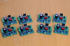
Spent the day soldering up eight Modulus-86 Rev. 2.0 boards. I average a little over an hour per board in assembly time.
The four on the left have a gain of 23x (27.3 dB) and are for use with a MiniDSP. The four on the right are built with the default gain of 10x (20 dB) and I intend to drive those with a Focusrite Saffire PRO24 professional sound card.
I think I may just crack open a bottle of microbrew and call it a day.
Tom
Attachments
- Home
- Amplifiers
- Chip Amps
- Modulus-86 build thread