Discovery: The feedback resistor located on the original model from years ago, measures at 114k. The first post should have specified feedback resistor in the range 100k~114k.
Second discovery: Hand cramp from the ohmmeter! It absolutely doesn't matter if you buy 1% metal film, 5% carbon or any combination thereof--they all lie. It takes at least 100 resistors to find some that match.
Third discovery: Resistors with weird values are fantastically easier to match--If you buy a value that's only available for 1% resistors, you get 2% resistors. However, if you buy any "standard" value, you may get a whole bag of 10% randomness with a 1% paint job. For example, if you want 100k metal film, buying 99k metal film could be easier to match in half the time.
If only someone would have told me that earlier. 🙂
. . . When the PSU is running at full voltage the bulb filament is hot and bleed current is set by the hot bulb parameters.
after shutdown the voltage falls and the bulb cools and the resistance drops and the bleeder tries to pull a more constant current rather than an exponentially reducing current. When down to just a volt or two the bulb will be drawing ~3times the current that a fixed resistor bleeder would be able to. . . .
OMG!! Thank you! This explains the odd little DC powered light bulbs cabled nearby the rectifier in some receivers.
My LED does something different. Its backwards to your example, but it shunts more dirty dc than clean dc. As they are run up to 1/3rd capacity, they will "attack" any noise. For example the 1156 LED replacement bulbs that mistakenly set RV's on fire because most RV converters are half wave (12vdc+6vac=18v and overrun). Perhaps I should have used a more durable 1/2w LED instead of the 1/6w LED?
I'd sure like to try that light bulb trick too.
But I'm onto working on the amp, and point-to-point has proved challenging. I can't figure out how to make the power rails even/same length and don't know if that is even necessary. If a straight bus is run across three chips, the center chip will have the highest exposure to the power supply cable. Is that a concern?
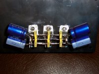
Amplifier photo, regular parallel stretched out to make triple parallel
Here's what I came up with for power circuit. I just stretched the Parallel LM1875 out to make room for triple parallel. It is still tiny.
Does it really need 6 of radio grade 100nF?
Will this arrangement do for power circuit? Suggestions?
Here's what I came up with for power circuit. I just stretched the Parallel LM1875 out to make room for triple parallel. It is still tiny.
Does it really need 6 of radio grade 100nF?
Will this arrangement do for power circuit? Suggestions?
Attachments
It might be coool if you mounted everything on a blank pcb, dead bug style, and used the pcb as a ground plane. Or, if it's more convenient, and it's a one-sided pcb, mount the stuff on the fiberglass side and drill holes to the other side for grounds.
Wow, imagine using a two-sided board for a single-supply circuit so you could have both power and ground planes. But you might need to etch or otherwise remove small "anti-pad" areas for holes to the other side.
Wow, imagine using a two-sided board for a single-supply circuit so you could have both power and ground planes. But you might need to etch or otherwise remove small "anti-pad" areas for holes to the other side.
Chicago style? I'll bet your radios are excellent!It might be coool if you mounted everything on a blank pcb, dead bug style, and used the pcb as a ground plane. Or, if it's more convenient, and it's a one-sided pcb, mount the stuff on the fiberglass side and drill holes to the other side for grounds.
Minimum etch, shielded? WOW!! 🙂Wow, imagine using a two-sided board for a single-supply circuit so you could have both power and ground planes. But you might need to etch or otherwise remove small "anti-pad" areas for holes to the other side.
Your insight amazes me. Although I want to to do a single supply parallel LM1875 on a different thread soon. . . I'd also like to complete this split rail amp here, And, I'm worried about it.
Actually, I'm stuck.
From the photo of post #28, the 100nF//100nF//100nf section looks like a clumsy generic guess gracelessly scaled up three times. Isn't the center extraneous? From here, what it looks like I should do is 100nF between each chip (100nF//100nF per rail). What do you think is best? Isn't there anything more graceful than painting it over with a crowd of 100nF caps? That doesn't look either optimal or specific. Is 100nF always the correct value, no matter how many there are? Help?
Thank you!
Are you asking about the power supply bypass caps, at the chips?
See the section on "Power Supply Bypassing", here:
Analog Devices : Analog Dialogue : PCB Layout
From that, it looks like the bypassing should go from power pins to LOAD GROUNDS; i.e. load ground should be connected right at the bypass caps' connection to the ground plane.
But notice that the classic "alternate connection" topology, from rail to rail, sounds like it might improve distortion performance, at the cost of higher-voltage caps.
As you can see from the link, you might want to use multiple values of caps, in parallel, maybe especially if high-speed (fast-changing) energy will be present. Maybe you could think fast audio edge (rise/fall) times for that (and scale up the cap values), but RF and other high-frequency junk will also be present, basically always. On another note, I don't know offhand if it might also be beneficial to use multiple larger-value caps in parallel, to better-cover bass/mid/treble audio frequencies. If in doubt, or since I know that you like to experiment, you could try .01, 0.1, 1, 10, 100, 1000, just for example, or maybe the classic 1-2-5 sequence "translated" for this purpose: 0.1, 0.22, 0.47, 1, 2.2, 4.7, 10, 22, 47, 100, 220, 470, 1000. Yeah, that looks like overkill, heheh. But then again I've never TRIED it. I guess I'd at least consider adding one or two more cap values, between your 0.1 and 470, just to see if your golden ears can detect a difference.
After all, the main "signal path" is the CURRENT that goes from power supply through chipamp then speakers. And I sometimes think of the bypass caps as a point-of-load power supply that has to supply at least the transients for that current, assuming we don't want the supply rails' and grounds' conductors' inductances to cause voltage disturbances when we try to instantaneously allow current to flow through them (and/or just not have the current be available precisely when demanded, as the chipamp opens and closes the "valves" between rails and ground). And if the transients are not available precisely when needed, then phasing and time-alignment might vary with frequency, which might mean the difference between good and exquisite. But that's all just guesswork, at this point.
At any rate, the point I was going to make was that the problem that you usually should watch out for, when choosing multiple bypass cap values (especially the small values), is that certain cap values might form a resonant LC circuit with the inductance of the supply rail (or ground) conductors (and whatever else contributes to the lumped inductance they see), at a frequency that can get excited by something that might happen to come along (fast edges, RF, switching spikes, etc), and tend to cause ringing or maybe even oscillation. It's a minor point, but sometimes it can bite you. I guess maybe you could apply fast-edged square waves and look for tendencies toward trouble, with a scope.
Last edited:
I consider this an important fact that many have either forgotten or never researched to become aware of.I sometimes think of the bypass caps as a point-of-load power supply that has to supply at least the transients for that current,
The FAST output is supplied by the tiny bypass caps if they are fitted in the correct location to provide almost instantaneous current.
The Medium spead output is supplied by the decoupling, again located so that they can meet medium speed demand.
The Slow output is supplied by the smoothing capacitors. Because these signal are slow changing, then the smoothing can be remotely located from the output devices.
Yes, that pile of yellow radio grade caps is certainly capable of making a powerful disturbance in their passband. If that wasn't the purpose, then the amp and its schematic needs repaired to a more user-friendly arrangement.Are you asking about the power supply bypass caps, at the chips?. . . At any rate, the point I was going to make was that the problem that you usually should watch out for, when choosing multiple bypass cap values (especially the small values), is that certain cap values might form a resonant LC circuit with the inductance of the supply rail (or ground) conductors (and whatever else contributes to the lumped inductance they see), at a frequency that can get excited by something that might happen to come along (fast edges, RF, switching spikes, etc), and tend to cause ringing or maybe even oscillation. It's a minor point, but sometimes it can bite you. I guess maybe you could apply fast-edged square waves and look for tendencies toward trouble, with a scope.
And that's what I'm asking about.
An interesting difference for rail to rail is that its not hard wired to the speaker return's powerful broadcast. So, rail to rail maybe really good for pre drive?. . . But notice that the classic "alternate connection" topology, from rail to rail, sounds like it might improve distortion performance, at the cost of higher-voltage caps.. . . I guess I'd at least consider adding one or two more cap values, between your 0.1 and 470, just to see if your golden ears can detect a difference.. . .
I will add a single Cornell Dublier, "Mallory" SEK 105c 4.7uF 250v electrolytic, rail to rail at exactly the point where the power supply dc cable attaches to the amplifier. Thanks for the reminder!
I consider this an important fact that many have either forgotten or never researched to become aware of.
The FAST output is supplied by the tiny bypass caps if they are fitted in the correct location to provide almost instantaneous current.
The Medium spead output is supplied by the decoupling, again located so that they can meet medium speed demand.
The Slow output is supplied by the smoothing capacitors. Because these signal are slow changing, then the smoothing can be remotely located from the output devices.
Yes. But don't we then still have to wonder about fast, LARGE transients? Maybe I should look at some actual music signals with fast-and-large transients such as snare rimshots or bass drum kicks, with wav files as inputs to an LT-Spice simulation of a power supply and output stage, that also includes all of the parasitics (and compare the response to an ideal one, maybe), with varying numbers of different-sized capacitors, and maybe especially larger number of small ones (again, with most all parasitics modeled). Either that or I could set up a physical circuit and dust off a good scope and try capturing some one-shot events to compare (or just use a pulse train as input).
This is another one of those cases where the science indicates tendencies but reality could be anything from "those tendencies are less than negligible" to "wow that makes all the difference in the world". I guess the first thing to do is dust off my back-of-the-envelope calculator, or try some quick-and-dirty spice comparisons of extreme cases. But, while spice and envelope backs are nice, even if I see a difference I still almost-certainly won't know if it would be audible or not. Maybe at that point I could hand it off to some willing golden-eared type. It's a bit frustrating to contemplate.
I have a few guesses. . .
Caps small enough to fill more quickly, also run out more quickly. So, the other interesting thing about it is the necessity of locating the speaker return away from caps that run out quickly, because we probably wouldn't want them in never charged condition.
Maybe it is just practical?
If you try to decide if "charges fast" like a small cap is better than "runs out slowly" like a battery, just spot the locations for both: See the predrive power size group at 100uF~680uF is so much different than the output power/speaker support size group at 3,300uF~10,000uF?
Charges fast (predrive group):
Choices for predrive power caps are extremely limited because you need just large enough for a flat response, but not terribly overlarge because that runs too hot and less clearly. After a just right size is installed, paralleling with same or larger caps doesn't appear to be harmful (no increase in heat, no decrease in clarity), but I couldn't tell you if adding more to that spot is useful. Notice the surprising omission of 220uF caps on the predrive power pins in the TDA7294 datasheet? That omission makes it unclear and hot running.
Practical: No need for either botique or eq if just right component values are used.
Runs out slowly (output transistor/speaker support group):
Choices for output/speaker power caps aren't so limited but should be large enough to support full bandwidth from the speaker. When the output power pins are absent, such as with LM1875, then assume the location is at speaker return. In our case, we're having the power supply pull dual duty as both smoothing and tank.
Practical: For big enough to support a speaker, the speaker return goes to the power supply 0v tap. Its also for a longer lasting amplifier.
P.S.
Its kind of "inconvenient" to compensate for current errors by adjusting voltage instead.
It may be fascinating to compare the power output of LM3886 BPA100 to LM1875 Triple Parallel, when driving a 2 ohm load, which happens when either is bridged to run a 4 ohm speaker.
I calculated identical output power. Is that correct?
Its finally dawned on me that National Semiconductor's heatsink recommendations would make sense if they didn't overrun their parts.
Perhaps NatSemi left the discrepancy as a clue that the marketing people wouldn't notice or censor? On the verge of beginning to overrun, semiconductors aren't yet stressed enough to drop voltage but do begin to run disproportionately hotter. Oh, that's a clue.
Reading my design has the small signal all at half the current of normal values, twice the capacitance and a generous heatsink. . . compare that a 15+15 transformer choice results in 220uF amp caps, 47uF feedback (ordinary textbook values become practical), and the manufacturer's heatsink advisement actually working. . . I'm detecting a ~10% voltage overrun in the datasheet. Correct?
Well, I guess they can't let everyone else brag and end up holding the short straw.
Last edited:
From your link:Are you asking about the power supply bypass caps, at the chips?
See the section on "Power Supply Bypassing", here:
Analog Devices : Analog Dialogue : PCB Layout
An externally hosted image should be here but it was not working when we last tested it.
Well, if you really want solid level signal grade, low impedance performance across the entire audio band for the power circuit directly at the chip, well that is extremely easy to do.
However, I'm completely confounded for power supply bypassing at pitches higher than the audio band. Shouldn't pitches higher than the audio band be met with a tiny RC filter on the power supply rails rather than flawless radio signal support????????? Or did you really want to support radio transmission with an audio amplifier? Most supply bypassing does seem to pretend that the audio amp is a radio transmitter. Is that the best way to go?
Well, just tell me what you want the caps to do and I'll find them without sending you to the botique or ham radio store. 🙂
That article and graph weren't specifically for an audio-frequency circuit. But in the case of high-frequency stuff, the bypass caps should pass it right on through to ground, BYPASSING the amplifier.
Last edited:
Cool. I have a missing value. It is approximately 22nF. It seems that I need to remove that center section of 100nF and trade for 22nF.
There is still an abrupt corner in the frequency as the 470uF HF failure mode rolls off gently and then slams into the brick wall of the 100nF high efficiency caps. If one did that with output caps the result sounds almost as good as a church bell in a tumble dryer. Hopefully the 4.7uF rail to rail cap can fill up that pothole and prevent the abrupt frequency corner (ringing).
More specifically: If it doesn't perform sufficiently, then a 0.5uF electrolytic can be placed on each rail. The HF failure mode of 220uF, 330uF and 470uF electrolytic will generally sum with the LF failure mode of a 0.5uF electrolytic, creating a flat response. Try 0.5uF electrolytic parallel with the big output caps of a bargain grade Via Tremor sound card and get a nice surprise.
Notes:
Input and bridging:
The phase inverter bridge adapter is getting some attention at this time:
http://www.diyaudio.com/forums/solid-state/200325-fet-based-phase-splitter.html
The DRV134 isn't the only option.
Alternative chips:
"OEM Replacement" FAKE LM1875, TDA2040, TDA2050, TDA2052
They're not LM1875. Let's address the differences now please. These MUST have lower voltage. Use the TDA2040 datasheet for voltage and therefore transformer purchase decisions. Change my 470uF caps for 330uF or 220uF for brighter clearer sound on these chips so that you won't encounter a "recessed" presentation that's not accurate. Use a "low impedance" type, such as Nichicon PW or a similar Panasonic. Likewise change my 4.7uF 250v electrolytic rail to rail cap to a 2uF 100v polyester.
Here, at the power circuit is where you avoid buying an equalizer but the needs of different chips are different for each model of chip.
Authentic TDA2052 will be double-parallel, not triple parallel, but the fake will need to be a triple since there's no other guarantee on current handling.
For these chips, we're talking about mid-fi products hacked to nearly hi-fi because of clean power, so consider adding a PI filter plus tank section for voltage drop, mild current limiting and much cleaner power, all of which is good for these chips. Fortunately 35v caps at your power supply and 25v for the rest is very inexpensive (note that you can certainly use higher rated parts if you wish for longer lasting). Although you may expect less power output from these, its not as much concern after bridging is complete. At speaker output, there is only a few decibels of difference between these versus the real thing.
Don't forget the flyback diodes!!! See the TDA2030 datasheet for flyback diodes to prevent the "OEM Replacemnet" (FAKE!!!) LM1875 from self destructing. And please use lower voltage than LM1875, or else kiss the speaker goodbye. Fakes are made for selling, not for lasting. You aren't guaranteed onboard flyback diodes.
Add your own.
On my point to point construction illustrated by an earlier photo, add the flyback diodes Before you add the 0v/ground rail. After that, the 0v ground rail with the 100nF (and/or smaller) caps on it, is made as a unit (with the caps aboard) then set into place. Your smaller 220uF caps on the power rails will make a more elegant fit, but the prospect is similar, and easier than it looks.
My design is a specific exploitation of LM1875 and not expected to work for other chips without adaptation. There are varying degrees of inbuilt stability enhancement, which, if present will sound better at Lower Gain. For example, LM675, low gain sister to LM1875, is this way. Don't set a near unity stable part to high gain because audio results are as horribly boring as putting gain on a dedicated buffer chip product. Likewise, you may have to drop the 100k feedback and input load resistor value down to 56k and likewise drop the 3.3k down to 2.2k, which is a "not as far off" guess, since it is closer to averaged textbook values. Op-amps all have their own different optimal support circuit, regardless of whether they are pin compatible or not. Basically, other (and fake) chips will use lower values, lower gain, cleaner power, lower voltage.
If in case the chip just isn't good enough for high gain and not stable enough for lower gain, add picofareds value cap between inverting input to non-inverting input, set parallel with your feedback resistor, to help support stability at lower gain. As a bonus, all three chips running triple parallel now have something in common. They're supposed to be identical anyway.
Now, don't buy the fakes on purpose, but if you happen to have mistakenly purchased 12 or more of them that came from the same tube or batch, install flyback diodes, and use lower voltage, then this project will probably make them useful. Sound quality will still beat almost every mass market retail store amplifier, and by far. But it won't take on the BPA200 for power, nor will it cost that much either.
There are 2 different fakes. One is much like a lovely old NEC, that would blow up on too much voltage, but otherwise work well. It is native to 4 ohm current handling as demonstrated by its typical high impact shatpants bass that most chips don't do. Use it if you have it, but seriously decrease transformer voltage. Try a 12,0,12 transformer with that one.
The other is a very unfortunate thing made with the same trash quality as NTE and that one is not expected to work triple parallel because of careless manufacturing variances.
The two fakes are almost visually identical and I can't tell which is which.
As a last note on "OEM Replacement" aka FAKE chips, I think that they are not as cost effective as authentic chips. You have to use a greater amount of better quality parts to support them (for clear playback) and still didn't get a hundred watts for your efforts. The fake amp isn't worth as much. Bear that in mind when this all shows up on ebay. 🙂
Output resistors (for paralleling):
For real LM1875 or for fake LM1875, the 0.15 ohm emitter resistors are probably overly optimistic. In real life, manufacturing varies more than that. Start with 0.22 ohms, and your chips will be grateful for the relief, at the cost (?????) of a slightly more laid back sound. Fakes may have to use 0.33 ohms or larger due to increased manufacturing variance. You may also have to do some "manual labor" quality control that wasn't done in the production line.
Last edited:
Question:
68k input load at each chip for lower noise and better bass?
If not, then how about 270k~290k at each chip?
Or, is a single point input load better than 3?
68k input load at each chip for lower noise and better bass?
If not, then how about 270k~290k at each chip?
Or, is a single point input load better than 3?
Single point versus 3-points input(s)?
Oh, you mean you don't have the three paralleled chipamps just after a fast opamp, but inside its feedback loop?
Just kidding, although you should definitely try that sometime (after you get ONE working that way), if you haven't already tried it.
Usually, one input resistor (to ground) is used (just after the input coupling cap, forming RC high-pass with very low cutoff freq = 1/(2.Pi.R.C) to keep out DC and sub-sonics) and then there are exquisitely-matched (0.1% or better, and with very low temperature coefficient) 1K-or-so resistors in series with each chipamp input pin.
In AN-1192 (national.com) Fig 6 they used 1 uF series and 47k to gnd, giving 3.39 Hz high-pass. I would probably prefer no higher than 2 Hz or so (always keep filter cutoffs 10X away from desired-to-be-unchanged frequencies). But I would also prefer to make the R as low as I could (for lowest self-generated resistor noise(s)), as long as the source could drive it well-enough (or maybe just add a unity-gain input buffer before the coupling cap, to cover all possible sources).
- Status
- Not open for further replies.
- Home
- Amplifiers
- Chip Amps
- Need help with Triple Parallel LM1875 dynamics amplifier.