Just made mods to a Z5500 pod PID R-547 to work on a Z5500 sub PID R638
The R-547 POD uses Pin 7 as the turn on for the sub, it is a momentary Hi pulse some posts say +5 volts.one pulse is on pulse again goes off. the same holds true for mute which is a + voltage.
I think is was 3.5 volts on my meter I forget, the point is this pod does control by going hi and the sub I have needs to go low to ground. Also the power on to ground is done by pin 6 wire which was missing on the go hi pod I have. My simple fix was to remove two wires from the pod board wire number 7&8 this stops the grounding of the hi signals.
Wire 7 is the enable of sound to come out of the woofer and 8 is the enable center channel to come on. By jumping pin 6&7 on the input board in the woofer I had a path back to start and because I was just plain lazy I tied wire 8 to7 it in the pod for center turn on but if you wanted to I am sure you could just use one of the wires for the replacement for the missing wire 6 and then tie the mute of the sub and the mute of the center channel together and use a circuit placed in the pod or the sub to use the the hi mute on to ground pin 7&8 to enable.
Now to get the unit to turn on I just used a small npn signal transistor (just about anything will do you have laying around) and a small reed relay DG1A12BW which is 1 amp and 12 volts I just so happened to have. I hot glued it in the pod dead bug style top down legs up out of the way. and soldered the emitter and collector pins of the transistor to the relay pins the emitter to the grounded side of the relay contact and the collector to one side of the coil adding a dropping resistor to the other side of the coil contented to 18+.
I got my signal on form the blue side of the pilot light. the connections are as follows, starting from the light a dropping resistor maybe 33k to 39k and a 2n4148 diode(band points at transistor in series for back protection (just enough voltage to make the transistor turn on) to the base. The emitter to ground and the collector in series with the 12 relay and an appropriate dropping resistor to the 18+ source in the pod to achieve the desired voltage at your choice of a relay. Don't forget to add a reverse diode (band points to B+) across the coil for kick back. The2n4148 was ok for my relay.
Now just tie one side of the SPST Normally open contact to ground and tie the other to the (white and blue wire in my) pod 7&8 .When you now turn the pod on the small amount of signal taped off the blue side of the light will turn on your transistor turning on the relay and grounding wire 7&8 and with the jumper in the sub from 6&7 it will now ground all three pins resembling normal operation except if you put it in mute the sub will still play. And as i said above if you wanted that feature you would have to add a little more circuitry to use its high to open the ground of wire 7 in the sub to mute and the jumper you used from 6 to 7 would have to be changed to 6 to 8 being used to replace missing 6 and 7 going hi high when you hit mute .
I hope this is not to confusing i wrote this out instead of adding a picture because only menbers can see picks I truly hope this helps all the questions as to why my replacement pod did not work or if you are using a different one also remember some pods from different models did not use 18+ and 18 - Ps. this wrong pod did light up and come on when plugged in to the sub just no sound or power on
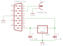
Thank you guys so much for this thread. I just made a sub preout adapter for my Z5500 (spring clip R540). I used the schematics from post 461 (along with others). To make the 5v for pin 8, I ran the 8v from pin 10 into a 7805 regulator (I had some laying around). I soldered it to a 15pin female dsub to avoid taking the sub apart (my pod still works, I just want to use the sub with a new receiver). The adapter works great as long as the rca plug pins are not left floating (left unplugged you get the nasty tone others have mentioned). I have attached my schematic for others to use if they want to build one. Thank you all for your hard work.
Attachments
Hello
I created a video in German. I show how the Z-5500 as remodels active subwoofer.
I have created two more videos, I show how to modify the cable.
Here is the link: Hacking the Logitech Z 5500 Control Panel Problem - German - Aktiv Subwoofer umbau - TimoMachts - YouTube
Have fun
I created a video in German. I show how the Z-5500 as remodels active subwoofer.
I have created two more videos, I show how to modify the cable.
Here is the link: Hacking the Logitech Z 5500 Control Panel Problem - German - Aktiv Subwoofer umbau - TimoMachts - YouTube
Have fun
Video Tutorial
German Video-Tutorial
Hacking the Logitech Z 5500 Control Panel Problem - German - Aktiv Subwoofer umbau - TimoMachts - YouTube
German Video-Tutorial
Hacking the Logitech Z 5500 Control Panel Problem - German - Aktiv Subwoofer umbau - TimoMachts - YouTube
Bypass successful! Sound Card to Sub. pre-636
Thank you EVERYBODY for you contributions to this thread since 2007. Truly inspirational!
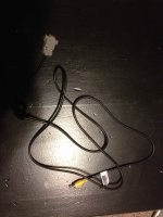
I too have a pre-636, spring-clip version Z5500 with dead control pod. My goal was to create a bypass cable going from my computer sound card straight to the sub, with no internal sub mod, and still having 5.1 surround, yes all six speakers working, including center and sub working perfectly, and independently, just like they should.
The posts that helped me the most were knexkid, Toffmonster, fluxarc , Sstevensn72 , and the final big puzzle piece, foodbag, the key being the 7805 voltage regulator, and not directly grounding pin 8. Thank you all for your help!
My bypass works perfectly, all six speakers. Front Left, Front Right, Rear Left, Rear Right, Center, and Sub all working, tested independantly using Realtek test screen where you can select each speaker and hear it play. I also added pots to control volume, just as everyone else recommended. I recommend too, as it is very loud. Here is youtube video of my bypass in action.
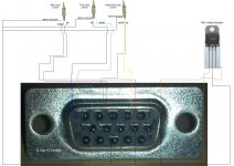
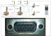
The only thing that I noticed was my D-Sub female connector numbering is backwards from what this forum suggests. I've attached my schematics for both no-pot, and with-pots. You can see my D-Sub connector with embossed numbers. They are definitely backwards, but this works great!
I hope this post helps someone like all of the others did for me. Good Luck!
Thank you EVERYBODY for you contributions to this thread since 2007. Truly inspirational!
I too have a pre-636, spring-clip version Z5500 with dead control pod. My goal was to create a bypass cable going from my computer sound card straight to the sub, with no internal sub mod, and still having 5.1 surround, yes all six speakers working, including center and sub working perfectly, and independently, just like they should.
The posts that helped me the most were knexkid, Toffmonster, fluxarc , Sstevensn72 , and the final big puzzle piece, foodbag, the key being the 7805 voltage regulator, and not directly grounding pin 8. Thank you all for your help!
My bypass works perfectly, all six speakers. Front Left, Front Right, Rear Left, Rear Right, Center, and Sub all working, tested independantly using Realtek test screen where you can select each speaker and hear it play. I also added pots to control volume, just as everyone else recommended. I recommend too, as it is very loud. Here is youtube video of my bypass in action.
The only thing that I noticed was my D-Sub female connector numbering is backwards from what this forum suggests. I've attached my schematics for both no-pot, and with-pots. You can see my D-Sub connector with embossed numbers. They are definitely backwards, but this works great!
I hope this post helps someone like all of the others did for me. Good Luck!
Attachments
Hi, maybe somebody knows a solution,
my preamps was damaged and i start to turn them off and go after the preamps to the amps.
but now i got a Problem.
i hear the woofer working when i swith him on, but i dont get a Sound. if i go direct after the preamps.
my other Speakers are working fine.
could it be that the woofer got two preamps and amps?
and does somebody know where i Need to solder them?
greetings
Lucas


Hello,
Merry Christmas everyone!
I read all your instructions here on how you can make the Z5500 subwoofer an active independent sub, but i can't trust my skills in electronics and i even don't have what i need to make the modifications.
Is anyone willing to help me and create an adapter to use the Z5500 sub on an AVR with pre-out RCA, please? not for nothing, of course.
I can make the payment via PayPal, i really need this adapter and here in Romania i don't have any chance to get it.
Thanks, Robert
Got mine working - now some fine tuning
Hi folks,
Thanks a lot for this great thread!! It helped me to get my R512 (early clip) running again after a lightning strike wrecked my Pod. I first connected pin 7 to +5v on the pre-amp board. Worked but gave some crackling noise in quiet moments. Then I did it like Toffmonster did it in Post #312 as I have exactly the same board. This gives a cleaner sound although LFr distorts as soon as the volume is set to more than 30% (windows 7) and setting the volume to 100% only gives my a moderate output volume with many distortions. I checked the voltage of the orange cable and it's not 5V but more like 3.5V. Is it possible that by connecting the orange cable to the resistor like in post #312 drops the voltage for the pre-amp so it can't work with louder signals? Then the solution with a 7805 connected to 8V would be a better solution. What's your experience? Can you get the same punch out of the box with no distortions with a 7805?
hello,
well i replaced a bad solder on a cap and my documentation wasn't that great starting out. Anyway, i am putting it back together and i forgot the order of the wires in the clamps coming from the main board and the toroidal transformer, two black and one blue from the board, with the opposite coming from the transformer. Now i see from pictures its grouped in a set of blacks, a set of blues and then one blue and one black wire in the clamp. Anyone have a picture or can explain the order quick?
Thanks
I have a question that may seem dumb. I have a 240VAC Z5500 system (R832 - somehow I have spring clips though - maybe it was the AU edition spring clip no matter how old or new? anyway) .
My question is: Can I connect the pod of a Z5500 110VAC to my Z5500 240VAC system? I can get a cheap 110VAC system and try to use the pod for my system IF it works but I am afraid of frying something if I try to plug in the 110VAC pod into the 220VAC Z5500 system. I will make sure the 110VAC system is the spring clip edition and try to get its R number too but interestingly, I got hold of a R031 sub and the pod of the R831 works with it just fine (spring clips model on both 240VAC). I understood people found (german link to YT?)that from 636 on the pods wont work with older models. Anyway my prob is whether 110VAC and 240VAC pods are interchangeable...
My question is: Can I connect the pod of a Z5500 110VAC to my Z5500 240VAC system? I can get a cheap 110VAC system and try to use the pod for my system IF it works but I am afraid of frying something if I try to plug in the 110VAC pod into the 220VAC Z5500 system. I will make sure the 110VAC system is the spring clip edition and try to get its R number too but interestingly, I got hold of a R031 sub and the pod of the R831 works with it just fine (spring clips model on both 240VAC). I understood people found (german link to YT?)that from 636 on the pods wont work with older models. Anyway my prob is whether 110VAC and 240VAC pods are interchangeable...
I have a question that may seem dumb. I have a 240VAC Z5500 system (R832 - somehow I have spring clips though - maybe it was the AU edition spring clip no matter how old or new? anyway) .
My question is: Can I connect the pod of a Z5500 110VAC to my Z5500 240VAC system? I can get a cheap 110VAC system and try to use the pod for my system IF it works but I am afraid of frying something if I try to plug in the 110VAC pod into the 220VAC Z5500 system. I will make sure the 110VAC system is the spring clip edition and try to get its R number too but interestingly, I got hold of a R031 sub and the pod of the R831 works with it just fine (spring clips model on both 240VAC). I understood people found (german link to YT?)that from 636 on the pods wont work with older models. Anyway my prob is whether 110VAC and 240VAC pods are interchangeable...
Well I got it and tried and while it works, the sub did nto turn on. Probably because of the R mismatch. If my current controller dies I will follow the instructions to try to make it turn the sub on.
I made a cable like this:
An externally hosted image should be here but it was not working when we last tested it.
And ONLY the center speaker is working. Any ideas?Did anyone ever sucessfully create a pre out cable or connection for the RCA version of the Z5500? something like post 482 or 379? I cannot get this to work for the life of me. I only want to get the sub to work as an active sub for my receiver. Can anyone help??
I also have a RCA version of the Z5500 (M/N S-0115B on the back and 111863-0436R on the bottom). Posts #482 and #485 looks like the perfect solution, but I haven't tried it yet. I also want to create an active sub-only version of the Z5500. Any reason why the solution won't work?
Hello all, first sorry if my question is not for this thread.
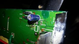
I have z-5500 speakers and for some time now the subwoofer starts and stops playing randomly, all other speakers are ok. So I decided to open the SUB and check what is happening. I saw L600 coil on the picture below is ripped from one of the sides. And the subs reacts on moving the coil, but when I moved the coil the copper wire has ripped completely. So My question is what exact kind is this coil L600 and also there is broken smd capacitor C600. What is the value of that capacitor.
Thank you.
An externally hosted image should be here but it was not working when we last tested it.
An externally hosted image should be here but it was not working when we last tested it.
An externally hosted image should be here but it was not working when we last tested it.
Hello all, first sorry if my question is not for this thread.
I have z-5500 speakers and for some time now the subwoofer starts and stops playing randomly, all other speakers are ok. So I decided to open the SUB and check what is happening. I saw L600 coil on the picture below is ripped from one of the sides. And the subs reacts on moving the coil, but when I moved the coil the copper wire has ripped completely. So My question is what exact kind is this coil L600 and also there is broken smd capacitor C600. What is the value of that capacitor.
Thank you.
An externally hosted image should be here but it was not working when we last tested it.
An externally hosted image should be here but it was not working when we last tested it.
An externally hosted image should be here but it was not working when we last tested it.
Attachments
No 8v z5500 Control Pod
Hi, hope somebody can help
My control pod don't turn on. After read this thread, I have tested the voltages that the z5500 control pod needs to run (+18v, -18 v,+8v). +18v and -18v (aprox) is present but instead of 8v the control pod receive 1.5v. I have tested the bridge rectifier AMI52 706v (tested out of the sub circuit) and it is ok, but if I'm not mistaken, the AC pins are shorted. The question is if I can replace this +8v with a common AC - DC adapter.
Thanks
I've seen all the awesome work done by so many of you, so I'll ask this favor:
I bought the subwoofer with all the electronics inside, no satellite speakers nor controller included.
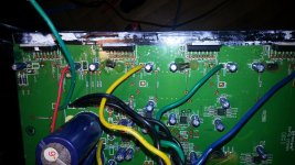
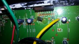
This is the problem: toroidal transformer wires were cut and I have no idea on how to hook them up.
So far I think this has to be done:
The toroidal transformer has white and black wires (ac input I suppose)
Black/yellow/Orange where (I suppose) black is ground center tap that goes to the main board? Yellow and orange go to the rectifier diodes. Is this correct?
Now, I see that the toroidal transformer has a couple of blue wires... for which i have no idea where they go, although I've seen that at least one of them goes to the board, to a small rectifier...
Or am I missing something?
This is what I mean...
I hope someone can help me out with pictures of your transformer-main board pictures.
btw, my Z5500 is the spring type.
Sorry for my bad English.
I bought the subwoofer with all the electronics inside, no satellite speakers nor controller included.
This is the problem: toroidal transformer wires were cut and I have no idea on how to hook them up.
So far I think this has to be done:
The toroidal transformer has white and black wires (ac input I suppose)
Black/yellow/Orange where (I suppose) black is ground center tap that goes to the main board? Yellow and orange go to the rectifier diodes. Is this correct?
Now, I see that the toroidal transformer has a couple of blue wires... for which i have no idea where they go, although I've seen that at least one of them goes to the board, to a small rectifier...
Or am I missing something?
This is what I mean...
An externally hosted image should be here but it was not working when we last tested it.
I hope someone can help me out with pictures of your transformer-main board pictures.
btw, my Z5500 is the spring type.
Sorry for my bad English.
- Home
- Amplifiers
- Chip Amps
- Hacking the Logitech Z5500