Hi,
I have been working for the past several months on a new three-way speaker system that will be powered by 6 LM3886 amps.
Originally I thought it would be best to put the active filters for each channel on a separate board, then do 6 amp boards.
Recently I changed my mind and decided to incorporate an input buffer, a high and a low pass filter, an output buffer with volume control and finally the amp circuit all on the same board.
The reasoning behind this is that It will be cheaper to have 6 small boards produced that are identical, and it makes things much neater.
Components can be left out of the portions of the board that will not be used. Only the high pass component need go in the high pass board, and so on.
I have adapted Rod Elliot's P09 24 dB/octave filter and used his implementation of the LM3886 (P19). I have come up with the following schematics, the first is the filter section.
Thoughts and comments either positive or negative are welcome. I want this to work right the first time.🙂
Attachments
Keep in mind that the LM3886 is itself an op-amp so you can wrap a 2nd order filter around it and eliminate an op-amp -- the fewer the better... with a little finessing you should be able to build a 3rd order filter around the power op amp....
dave
dave
Hi,
if you can arrange the components R3 & 4 and C2 & 3 to fit a DIL header and arrange the PCB with a DIL socket, you can swap out different headers with alternative frequencies and or Q values.
You can also swap C for R in each header by simply turning it around to convert from low pass to high pass (but this screws up the Q if you go for unity gain filter topology). If you go for equal value S&K then Q is set by the opamp gain and the Rs&Cs control just the frequency and not the Q.
This arrangement is very easy to change and saves a lot of PCB space by avoiding the need for the extra dual opamp and it's components.
Have you read the filter threads for the previous group buys? There is a lot more than just turn-over frequency and slope to consider when activating your drivers.
I went further and put the bridge rectifier and storage capacitors on the board as well! Needs careful layout though.
Hi,
forgot the other part of your question,
You appear to be building monoblocks dedicated to each driver.
If at some later time you change the driver(s) then the more flexibility you put into your crossover and equalisation then the more chance you can reuse the monoblocks with minor "software" mods rather than a complete rebuild.
I like the idea of each amp dedicated to the driver. But suggest you build one and get it working (with the driver) to your satisfaction before laying out all the copies.
Gives much scope to meeting my big advice:- use VERY SHORT speaker cables.
planet10 said:Keep in mind that the LM3886 is itself an op-amp so you can wrap a 2nd order filter around it and eliminate an op-amp -- the fewer the better... with a little finessing you should be able to build a 3rd order filter around the power op amp....
dave
Excellent idea Dave, I hadn't thought of using it.
The other filter sections are unity gain, the amps at 27dB gain - any adverse effects?
AndrewT said:Hi,
if you can arrange the components R3 & 4 and C2 & 3 to fit a DIL header and arrange the PCB with a DIL socket, you can swap out different headers with alternative frequencies and or Q values.
Another good idea. The use of sockets would vastly simplify the "tuning" process. The component values in the schematic are not the actual ones I will use, as I haven't determined the ideal crossover frequencies yet.
I want the board as simple as possible though, with the shortest runs and single sided. The DIP sockets might mean a lot of re-routing to accommodate.
As for changing the speakers some time in the future...without a doubt I will, as I get tired of things eventually. Chances are I would re-do the active amp at that time also.
consort_ee_um said:I went further and put the bridge rectifier and storage capacitors on the board as well! Needs careful layout though.
I have started to build a new chassis that will house the power supply seperately, along with the power supply for my sub amp and anything else I wish to add in the future. It will have:
1/ 50-0-50 800VA (+-70V)
1/ 30-0-30 300VA (+-42V)
2/ 25-0-25 120VA (+-35V)
1/ 12.6-0-12.6 60VA (+-15V regulated)
In the chassis will be the bridges and filter caps. Also should have a soft start circuit capable of handling 1500VA.
Pic of partially complete power supply chassis:
Attachments

Hi MJL21193,
The ones that I've built were LR4 @ 100 and 2k, modified from Siegfried Linkwitz's phoenix xover. A few things came to mind about your design:
- baffle step compensation
- use lm6172 or opa2132 opamp instead of NE5532, and include PSU cap bypasses from +ve to ground, -ve to ground, and +v to -ve
A question though about your schematics which show LP 300 and HP 3k, were you also intending to add LP300 + HP 3k for the midrange drivers in the 3-way?
trats said:
- baffle step compensation
- use lm6172 or opa2132 opamp instead of NE5532, and include PSU cap bypasses from +ve to ground, -ve to ground, and +v to -ve
A question though about your schematics which show LP 300 and HP 3k, were you also intending to add LP300 + HP 3k for the midrange drivers in the 3-way?
Hi Trats
My approach is to have pots to adjust the levels of all six channels, so that will cover baffle step (increase output to woofer)
The op-amps I have, so I'll stick with them. The NE5532 is good enough for this application anyhow - low noise.
Bypass to ground on both rails are in place (C13-C16) Could put one from rail to rail, say .1uF.
The values shown are temporary, as I haven't determined the optimal crossover freqs yet. The plan is for this to be modular,each board will be a self contained filter and amp for a driver. For example: the woofer will be driven by one with only the low-pass components on it. The midrange will use both high-pass and low-pass.
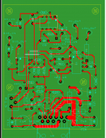
A sample board layout, based on the schemetics posted earlier. Something I did before I started this thread to figure out the board size. Took a while to figure out how to get it to a postable format.
One sided, just 2 jumpers. Finished board is 2.5" x 3" which is the perfect size forthe chassis I've built.
Once again - thoughts, comments, like it, hate it, or just don't care. It would be nice for some of you out there to look it over with a critcal eye, point out my mistakes.
Like I said earlier, I want this right the first time.
Attachments
MJL21193 said:
Once again - thoughts, comments, like it, hate it, or just don't care.
Well, I'm just overwhelmed with the response! 🙂
Maybe it's all been covered before, but searching I found nothing like this to suit my needs.
Nevertheless, I'll press on. I'll go with the board layout above, for better or worse.
Thanks to those who contributed.
Hi John. You could compact the layout a bit, unless you find it harder to work on a board with closely spaced components. Also, since each of the 2 op amp filter blocks (high pass and low pass) have the same basic component configuration (just with R's and C's switched) you could come up with one good, compact layout of that block and then copy it twice. It's also considered good practice to have your connections/wiring points on one side of the board, but certainly not necessary. I do like the way you used separate pos_15 traces going to each op amp V+ pin. You should try to do the same for the neg_15 traces. Grounding is also suboptimal because you chose to do a single layer board. Have you thought about using a double layer board? You could use one side as a ground place and the other for the traces. It will be trickier etching that yourself though, but probably worth the extra effort.
Hi Brian.
I'm working on a new layout, one that will increase the ground coverage, as well as widen the positive and negitive traces, and generally tidy things up.
I won't be etching these myself. I have found a place that will produce these boards for $15 setup plus $3.50/board. No silkscreen, but I can take care of that.
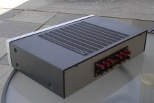
In the meantime, I have finished the chassis, except the power inlet (which I'm still working on).
Here's a couple pics, front:
I'm working on a new layout, one that will increase the ground coverage, as well as widen the positive and negitive traces, and generally tidy things up.
I won't be etching these myself. I have found a place that will produce these boards for $15 setup plus $3.50/board. No silkscreen, but I can take care of that.
In the meantime, I have finished the chassis, except the power inlet (which I'm still working on).
Here's a couple pics, front:
Attachments
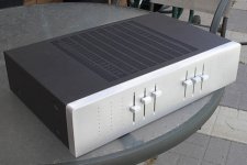

Aha! I was wondering how much fun you would have putting all those leds and sliders on an alu frontplate, but I see you used wood. Neat idea!😀
BWRX said:Nice chassis! Got those heatsinks from barred_boss on ebay, huh? 😉
Thanks. Yes, heatsinks from barred_boss = excellent deal. There is one full 12" piece of it in here cut up, with only a 1" strip left over. Not to waste anything, I used the that aluminum to make the slider knobs 🙂
- Status
- Not open for further replies.
- Home
- Amplifiers
- Chip Amps
- Active filter plus LM3886 - one board