Maybe Mario could say something. I use a toroidal transformer with 26v 0v 26v. I used a positive rectifier and a negative rectifier.. So I habe +30vdc,0v,-30vdc. I used regulators to produce +5vdc, - 5dc and a lm 7812 to produce +12vdc. All have a common ground.. I used +12 and common ground for the irs... And I think that's the problem.
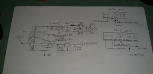
I modified my Power supply.I have a second winding, which is now used for the 12V.
The Negative is tied togehter with the negative rail.
The +-5V use a common center with negative and Positive rail..
Problem is now, that if i measure the osciloscope the 12V + and Negative rail, i have my clean 12V.
If i measure between +12V and common ground, the voltage isnt clean. Its flickering .
Is there a possibility to connect negative rail and common ground? Maybe with a ceramic cap?
This is my power supply. You can see how I check the cards outside the amplifier. Pay close attention to where you put and where you don't put the negative rail.
Sorry, in picture the winding for +/-5v have an unconnected pin, is obviously connected to GND.
Sorry, in picture the winding for +/-5v have an unconnected pin, is obviously connected to GND.
Attachments
Last edited:
So, here we go now.. Audio ground is connected to common ground.
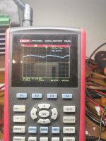
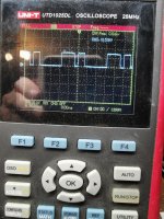
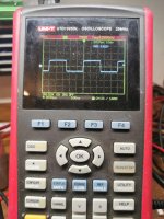
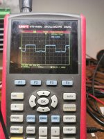
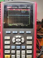
The first picture with the clean square wave is tl072 pin 1.
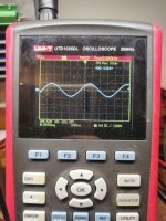
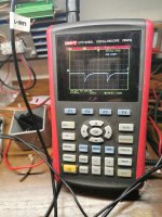
The second picture with the disturbed square is the lm 211 pin 2.the third picture with the sine wave is lm211 pin3.
I changed allready the lm211, but still the same.
The first picture with the clean square wave is tl072 pin 1.
The second picture with the disturbed square is the lm 211 pin 2.the third picture with the sine wave is lm211 pin3.
I changed allready the lm211, but still the same.
Attachments
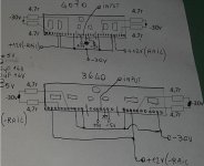
I'd suggest that you insert a resistor in series with the signal source. Something between 4.7k and 10k.
Also connect a 10k resistor between terminals 1 and 2 of the TL072.
Drive about a 1v signal into the series resistor (not directly into the driver board terminal).
You should see a relatively clean sine wave on the output of the TL072. Is that what you see?
Also connect a 10k resistor between terminals 1 and 2 of the TL072.
Drive about a 1v signal into the series resistor (not directly into the driver board terminal).
You should see a relatively clean sine wave on the output of the TL072. Is that what you see?
The first picture is pin 1 with black probe on negative rail. If I use common ground, it's floating below. The last two pictures is pin 11, first with black probe on negative rail. Then on common ground.. Still something wrong. The signal on pin 11 should look different..
Attachments
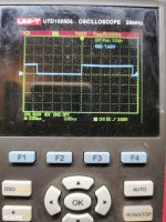
Yes, Iam driving a sine wave. It's going half down, half up.. So normal.. The square wave signal is on pin 1 of the irs. But I think maybe the input is too high. It's about 10v if I use negative rail for the black probe. If I use common ground, the amplitude is floating in the negative rail. That means, that the amplitude is at minus 20v.
- Status
- This old topic is closed. If you want to reopen this topic, contact a moderator using the "Report Post" button.
- Home
- General Interest
- Car Audio
- Test class d dwm drive board separately