Yes, i removed the transistor, now the reading is Ok. Its connected to Pin 4, first row of the drive board
Installed a D1303, it has a little smaller current, but i think it should work. Now i have lowside on each bank. Will install for test some irf064n
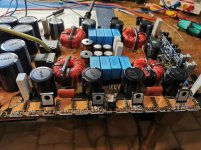
Usually when I happen to work on a Korean board of this type (with 2 D1302) I permanently remove the defective one, I create a bridge from the collector of the working one to the collector pad of the one I removed and I modify the base resistor of the surviving D1302 from 100k to 91k (changing this resistor is not strictly necessary). Keep in mind that you have 2 transistors because each manages one side of the driver card (each D1302 manages 2 IRS21844), I think they chose this solution because they believed that a single transistor was insufficient to shut down all the ICs, but I can to say with certainty that only one is enough and advances, in fact in some revisions of these boards, they mount only one.Yes, the collector has 5 Ohm to Pin 4 without the transistor. The Transistor is damaged
Ok, thank you for the Information. I had plenty problems to take the amp out of the heatsink. It seems, that the board is a little bit to wide for the heatsink. I want to reduce a little bit the sides of the board with a file. Do you had same problems? We needed three people. One was staying on the heatsink, one has pulled the board, another pushed the board..
It's happened with other amps. If you fish a couple of strands (one for each side to distribute force) of heavy cord (2.5-3 mm Dyneema/Spectra) under the board you can anchor the board/cord to a solid point and then you can pull/jerk on the heatsink.
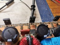
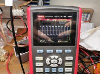
Tested today with a pair of irf064n. Signal looks good everywhere. Fets heating up, but I think in this case it's normal. The inductors are glued to the board. Twisting not possible. Anything else I can test, before reassemble everything?
Attachments
I don't know if the heating up is normal.
You have used +/-30v and IRFP064N are rated for 55v, so, is possible that the 5v of difference can cause heating but i'm not pretty sure.
Try with any 100v n-mosfet (IRF540N - IRF640N) .
After all, IRS21844S with a low voltage can drive everything (the important thing is that there is only 1 mosfet per bank). Next, if you get the operation without heating, you need to make sure that all gate, pulldown, VS resistors (2.2r 2w) are in tolerance and connected correctly. At that point, I see no other problems so I would mount the power diodes and try with proper high voltage and mosfet.
Ok, i have tried with the original FDA24N50F... They stay cold... I will continue now..Thanks a lot Mario and Perry
Ok, install power diodes and the lowest you can battery voltage for the firts power up.
If i remember, gzpa10000spl HC allow the minimun battery voltage of 12v for the start-up then, it can go lower once it is turned on completely., under this point remain in protection.
Other amps (same design but lower power) accept 11 or 10.5v.
Dont forget, use only one fet per bank (fda24n50f or irfp460lc).
This allow you to perform the first start up to see the class D operation for 3seconds for each stage, so you can extend the test time to 10 seconds, 20 seconds, so, install other fets and use a speaker to try to listen 10 second of music.....
If all ok, install all, install the board in the chassis and clamp all to the heatsink.
Now you can try to power the amp at full battery voltage (14,5v) and good current reserve.
If the amp survive at this.......you can use in the car...
ahahah
- Home
- General Interest
- Car Audio
- Test class d dwm drive board separately