Does the idle current on the distorted channels increase when you adjust their bias pots, like it will when you adjust the bias on the good channels?
How many channels failed initially?
Were the distorted channels ones that failed?
Do you have both positive and negative rail voltage on the output transistors of each of the distorted channels?
Two weeks to Canada?
What sort of scope is it?
How many channels failed initially?
Were the distorted channels ones that failed?
Do you have both positive and negative rail voltage on the output transistors of each of the distorted channels?
Two weeks to Canada?
What sort of scope is it?
Turning up the idle current adjustment on the two bad channels does rise the amp draw by 0.02A, but turning it up on the good channels takes it up way more.
There was just the one channel with a bad FET, I'm not sure on the other channel, as I didn't get a chance to run the amp at all. I got it used.
Yes channel 4 is the one that originally had the bad FET, and it has distortion. There are two new FETs in there now, and the driver is not obviously shorted, and tests out on my tester.
Yes all transistor pairs have + and - rail voltage.
Shipping could be faster, but you never know with customs and all.
I got a B&K 1541C 40 mhz analogue scope off eBay for $75.00 plus shipping. Hopefully is doesn't end up being another repair job!
You should have a capacitor in series with the test speakers unless they are high-power subwoofers.
Is there a reason that you can see that two channels are distorted when only one failed initially?
Have you checked all of the low-value SMD resistors on the main board near the output transistors?
Is there a reason that you can see that two channels are distorted when only one failed initially?
Have you checked all of the low-value SMD resistors on the main board near the output transistors?
Good tip about the cap...
No reason that I can see why two channels are out, but they could have been out all along, and I only found the one bad FET. I have never played the amp in my system, I picked it up used, and broken.
I poked around the small resistors, and didn't find anything off.
I did get the scope, and looked at the speaker out on all the channels. The two bad ones are putting out the upper half of the sine wave only.
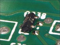
No obvious problem with Qx19. I don’t think I can pull it to really check without destroying it because it’s all surface mounted. I probed around and distortion starts at Q104, the input is clean, the output is a misshaped wave with a smaller bottom than top, and a notch in between. The good channels look clean on three pins of this chip. Kind of lost on this, but it seems that the problem is in the low level circuit.
Don't describe the waveform, post a photo.
You don't have to harm the SMD transistors to desolder them. Apply extra solder to two legs and heat both at the same time and lift the transistor. Then desolder if there is enough to bridge to the raised terminals.
You don't have to harm the SMD transistors to desolder them. Apply extra solder to two legs and heat both at the same time and lift the transistor. Then desolder if there is enough to bridge to the raised terminals.
Attachments
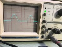
OK, posting pics, hope they work.
Looking at Qx04:
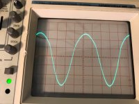
Pin 5 has this:
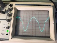
Pin 3 and 4 have this:
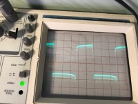
Pin one and two have this:Sign in - Google Accounts
Pin 4 goes to the collector of Qx07, which has no signal on the base or emmitter.
On the good channels pin 3, 4, and 5 of Qx04 have a sign wave on them, and a the same signal as pin 1 and 2 on the bad channel
Looking at Qx04:
Pin 5 has this:
An externally hosted image should be here but it was not working when we last tested it.
Pin 3 and 4 have this:
An externally hosted image should be here but it was not working when we last tested it.
Pin one and two have this:Sign in - Google Accounts
Pin 4 goes to the collector of Qx07, which has no signal on the base or emmitter.
On the good channels pin 3, 4, and 5 of Qx04 have a sign wave on them, and a the same signal as pin 1 and 2 on the bad channel
Looking at Qx04:
Pin 5 has a good sine wave
Pin 3 and 4 have the weird looking sinewave
Pin 1 and 2 have the squarish looking wave
Pin 4 goes to the collector of Qx07, which has no signal on the base or emmitter.
On the good channels pin 3, 4, and 5 of Qx04 have a sign wave on them, and a the same signal as pin 1 and 2 on the bad channel
Attachments
I don't know how we got to those transistors. The output isn't clean so the feedback to those transistors won't be clean.
Connect a load (preferably a subwoofer or dummy load) to the defective channels and post a photo of the output waveform. The FETs will have to be tightly clamped to the heatsink for this.
Connect a load (preferably a subwoofer or dummy load) to the defective channels and post a photo of the output waveform. The FETs will have to be tightly clamped to the heatsink for this.
This amp has global feedback. It takes the output signal and feeds it back to the differential amplifier (at the other end of the circuit) which compares the input and output signals and tries to correct for any distortion. It can correct for tiny errors but it's can't compensate when one/half of the output is missing.
This is an awful circuit to try to troubleshoot. It's FAR, FAR, FAR too complex. The newer amps do the same thing and and are much simpler.
This is an awful circuit to try to troubleshoot. It's FAR, FAR, FAR too complex. The newer amps do the same thing and and are much simpler.
- Status
- This old topic is closed. If you want to reopen this topic, contact a moderator using the "Report Post" button.
- Home
- General Interest
- Car Audio
- Rockford Fosgate 4600X series one power supply