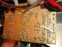
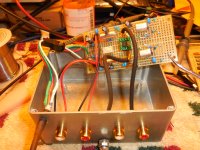
I have an OPA1656 story that may be interesting especially to whomever wants to build the RIAA preamp example in the apps section of the data sheet. I did build that and the slightly modified schemo is attached. I used the attached blank proto board. The Layout is attached. Of the three independent rails on each edge the outside L and R were used for -15V and +15V, resp. The inner two were 0V, center Gnd, branched at power entry at the top. The rails are heavily post-filtered and bypassed and the P/S is external. The DIP8 socket has 0.1uF X7Rs pin 8→gnd, pin 4→gnd and pin4↔pin 8. The enclosure is cast Al/Zn, at 0V and everything “grounded” only via the cable shields to the main preamp. I used polystyrene caps b/c they can be had surplus in 1% values. 000.0mV appears across the 47KΩ non-inverting input load resistors and at rest the finished unit is dead quite.
Now, my turntable is a full-auto linear tracker with internal mute switch used to short the ± moving magnet cartridge coil leads together while lowering onto and lifting off of the record surface. On the maiden voyage of my new external RIAA preamp I turned the system volume down; pressed Play on the TT and once the needle was down, slowly raised the volume to take a listen. Sounded GREAT. Turned-up the volume to let it “burn-in” while I did something else.
Once the side had finished I heard a tremendously loud POP-THUMP (tonearm lifting) and seconds later another very disturbing THUMP-POP (tonearm returned to rest). The mere action of the mute switch shorting and un-shorting the cartridge leads was causing a huge transient at the RIAA output. The 1656 just went berserk! “Somethings wrong and I have to use all my horsepower to fix it right now!”.
Of the op amps in my collection the massive misbehavers are the OPA1656, the LME49990 and the OPA1612. The completely docile op amps are the OPA2604, the OPA627, the OPA2107, the LM4562/LME49720 and the OPA2134. Those are fine.
Long-winded question for anybody is what’s the diff between these two groups of op amps that allows for such infinitely different behaviors in this very, very common circuit? In my case, my TT happens to have a mute function = I’m denied use of the 1656.
Attachments
Well, looking at your list of op amps, the completely docile list are almost all JFET-input devices (with the exception of the LM4562s which are bipolar). This leads me to believe there could be an issue caused by the back-to-back diodes across the inputs of bipolar (LME49990, OPA1612) and CMOS op amps (OPA1656). If a transient causes the op amp inputs to be pulled apart, the differential input voltage forward-biases those diodes causing a large input bias current. However, I would have thought the shorting switch on your turntable would prevent this. Is the pre-amp input also shorted to ground during the touch-down/lift-off of the tonearm?
Looks like you have a gain of 1,000 on the input offset voltage. Usual method is to use a capacitor in series with the opamp input terminal. As the input impedance is almost infinite pretty much any capacitor will do.
I would not use a mylar (polyester), ceramic or electrolytic capacitor. A value of .1 uF or larger should be fine. It will also help reduce cone motion from record warp.
You might also want to add a ground reference to the inverting input. But it can be a few megohms.
I would not use a mylar (polyester), ceramic or electrolytic capacitor. A value of .1 uF or larger should be fine. It will also help reduce cone motion from record warp.
You might also want to add a ground reference to the inverting input. But it can be a few megohms.
Last edited:
stratus 46: I will try that.
johnc124: No. The only shorting of signal is done by the mechanics of the TT. It's a small slide-switch slid back and forth by a cam. It's a bit gritty. I mentioned that the voltage impressed across the 47K by the 1656 + input was as zip as I can measure so I did not suspect DC current flowing through the cartridge's non-insignificant inductance.
johnc124: No. The only shorting of signal is done by the mechanics of the TT. It's a small slide-switch slid back and forth by a cam. It's a bit gritty. I mentioned that the voltage impressed across the 47K by the 1656 + input was as zip as I can measure so I did not suspect DC current flowing through the cartridge's non-insignificant inductance.
Looks like you have a gain of 1,000 on the input offset voltage. Usual method is to use a capacitor in series with the opamp input terminal. As the input impedance is almost infinite pretty much any capacitor will do.
I would not use a mylar (polyester), ceramic or electrolytic capacitor. A value of .1 uF or larger should be fine. It will also help reduce cone motion from record warp.
You might also want to add a ground reference to the inverting input. But it can be a few megohms.
Yes, the low pipe organ pedal notes down 'round 20Hz are rolled-off at 20dB/decade below that of the mid-band 1KHz level during the cutter/mastering process. in order to resurrect those signals the preamp applies a maximum gain of 1000 b/c the basic mid-band gain must be ~ x100. The input resistance of this preamp is not infinite. It's 47K ohms. And I have no "known" DC to block so I wanted to go DC direct if I could. I'm not sure what benefit a few megohms around C4 would provide.
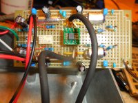
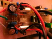
"Is that 47uF/35V cap in picture #1 (far left low side) looking domed?"
It sure is boss. Nice catch but, that is not a current photo. My bad in the company of experts. Jeese. Anyway the 47's were replaced by 220's as in the Layout dwg.
I don't have complete handle on the "Reply with Quote" thing yet.
It sure is boss. Nice catch but, that is not a current photo. My bad in the company of experts. Jeese. Anyway the 47's were replaced by 220's as in the Layout dwg.
I don't have complete handle on the "Reply with Quote" thing yet.
The gain of the op amp's input offset voltage is 1, not 1000, that is the purpose of C4.
If you have an oscilloscope it would be very helpful to see what the input signal to the preamp is during these events, and also how the output responds.
Completely correct re the DC gain. x1000 only kicks in with that organ note. Actually the choice of R4 and C4 causes a RIAA error at the low end as the datasheet points out. Increasing C4 reduces that variance from the standard. So I did increase C4 initially to 220uF non-polar but took it back to 100uF when I had the problem - but no help.
I owe two answers which I will get to tomorrow. Shorted RCA plug reaction and dual-trace scope image of the actual event.
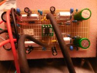
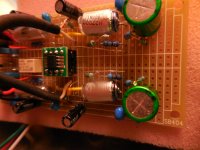
Was it reverse polarized and built up pressure? That white thick cable to its left looks like a minus PSU rail.
Indeed it was, sir. More current photos attached.
Attachments

John
He hears a pop. The gain on a change of some sub millivolt offset to zero will make a pop. The DC blocking capacitor is 100 uF, that gives enough time constant to allow a substantial popping noise.
The input 47K resistor and the cartridge DC resistance may of course lower the voltage created by the offset current. Which actually may be a bad thing if it was offsetting the voltage. Of course the input offset current is typical 10 pA which if compensated would require a 50 megohm resistor across the dc blocking capacitor and leakage current from the card and or capacitor makes that insignificant.
Adding any small film capacitor will show if the half millivolt offset is the problem. (Or 5 volts at the output!)
Last edited:
Sounds like some sort of oscillation issue that depends on the source impedance.
The cable that's shorted at the other end will behave as a transmission line resonator that apparently gets undamped by the op-amp. Chances are that an RC series network across the input can damp the resonance and fix the issue.
How long is the cable from the turntable to the phono preamplifier and what dielectric does it have?
Last edited:

Assuming you have a cartridge that requires a very low load capacitance (does it?), you could try something like 82 ohm in series with 47 pF across the input. You could also connect it as an RC low-pass filter between the input and the op-amp, that will give some extra rejection of picked up RF signals at the expense of a very small increase of the noise.
Old designs of decades ago had RF filtering. Today the aether is chockfull of RF and even modern designs by known designers lack RF filtering (add power on/off muting and DC protection to that). Modern silicon is way more wideband too. Some designs are proudly presented with plots going in MHz range…
Contradictory.
Contradictory.
Last edited:
John
He hears a pop. The gain on a change of some sub millivolt offset to zero will make a pop. The DC blocking capacitor is 100 uF, that gives enough time constant to allow a substantial popping noise.
The input 47K resistor and the cartridge DC resistance may of course lower the voltage created by the offset current. Which actually may be a bad thing if it was offsetting the voltage. Of course the input offset current is typical 10 pA which if compensated would require a 50 megohm resistor across the dc blocking capacitor and leakage current from the card and or capacitor makes that insignificant.
Adding any small film capacitor will show if the half millivolt offset is the problem. (Or 5 volts at the output!)
I don't disagree with any of this, I was simply clarifying that at steady state the gain applied to the op amp input offset voltage is 1. I'm still suspicious that an input transient is forward-biasing the back-to-back diodes across the inputs of the OPA1656 causing the input offset current to be several orders of magnitude higher than the typical value momentarily.
- Home
- Source & Line
- Analogue Source
- OPA1656 Phono Preamp: Split from OPA1656 thread