Here is the model with the green rail above. Although it may work, I feel that both the rail and the slider may be too complicated to be highly efficient.
.gif")
This is exactly where I was right at the beginning of this thread. I have the exact fomulas for the path of any point on the tonearm whose stylus end follows a Thales circle. These paths are not circles. Borrowing super10018 words, they are not doable for diyers, but require CNC machining accuracy. However they can be approximated by circles, typically by exactly specifying 3 points of the path. This will result in tracking error at the stylus end which may be small if care is taken. I am not interested in another approximate tangential tracking geometry. I want to achieve perfect tangential alignment everywhere.If a highly efficient rail guiding mechanism does exist, you may not need the additional link. Please see the green line.
View attachment 1005618
I read multiple comments that close agreement with the true tangential alignment is only required for the playable region of the disc. This may seem sensible on face value but turns out to be wrong advice for my purpose. This is definitely a case of looking at the bigger picture to see what is going on.
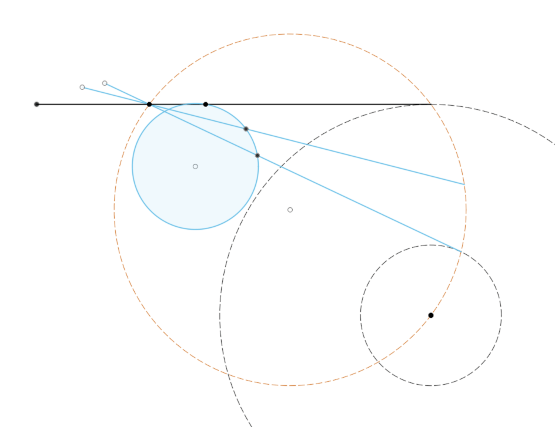
The bigger picture in this case means exactly that; follow the path of a point on the tonearm as the stylus travels the complete Thales circle. It reveals a curve which is non-circular but recognisable. This aha! will get you further. Once the recognition takes root, the solution to maintaining perfect tangential alignment with a circular guide path falls out. The “penalty" for this is the additional link. However it is one less link than the double Birch style solution. The sliding pivots will be the main constructional hurdle. The circular guide can be some kind of machined groove capturing a rolling bearing element.
The animation shows the relation between the rear (non-circular) tonearm path (dashed) and the circular guide path.
I don’t want to spoil the aha! moment for anyone, but if you have the software, see if you can plot the complete rear path (dashed) of the tonearm for the stylus completing a full Thales circle. Then also show the full guide circle path. I can post them later if requested.
Here is the mid tonearm link version. It is a much more compact guide mechanism/path with exactly the same tonearm positioning. This configuration has some favourable features. Notice all the relevant paths and pivots bar the mid-tonearm pivot, lie on the Thales circle. This is not a coincidence. Some serious geometric voodoo is at play. It will be the one I go with.The animation shows the relation between the rear (non-circular) tonearm path (dashed) and the circular guide path.
First, it makes no difference if the rear guide is a circle or non-circle. Adding one more link to convert a non-circle guide to a circle guide makes the structure more complicated. In the meantime, such conversion doesn't make the guide mechanism simpler. However, it is a personal preference. How efficient a rear guide is depends on the structure, not the shape of the guide. I don't think there is a strict rule for everyone and for all the designs.
In my opinion, it is unnecessary to pursuit zero tracking errors even it is outside of the playable areas. Again, it is a personal preference.
As I said before, the devil is in the implements. There are many geometries that may work, but not all the PT arms will sound the same.
In my opinion, it is unnecessary to pursuit zero tracking errors even it is outside of the playable areas. Again, it is a personal preference.
As I said before, the devil is in the implements. There are many geometries that may work, but not all the PT arms will sound the same.
Last edited:
You are missing the point. Possibly my explanation is still unclear. I will try again because you have put some serious effort into your builds and I respect that. Here I go again.First, it makes no difference if the rear guide is a circle or non-circle. Adding one more link to convert a non-circle guide to a circle guide makes the structure more complicated. In the meantime, such conversion doesn't make the guide mechanism simpler. However, it is a personal preference. How efficient a rear guide is depends on the structure, not the shape of the guide. I don't think there is a strict rule for everyone and for all the designs.
In my opinion, it is unnecessary to pursuit zero tracking errors even it is outside of the playable areas. Again, it is a personal preference.
As I said before, the devil is in the implements. There are many geometries that may work, but not all the PT arms will sound the same.
Perfect tangential tracking on the Thales circle requires any point on the tonearm apart from the stylus point, to follow a certain path which is not circular. Approximating these paths with circles will make the stylus depart from the Thales circle at almost every position, although the error can be made small.
The true paths of any point of the tonearm can only be recognised by following it outside of the playable area. This is purely for identification purposes. If you are unwilling to look, then of course you can't discover anything.
Once the true path(s) are recognised, there is a well known connection with rolling circles. This is where the circular guide path is discovered. The connection is exact, not an approximation at any stage. It is valid for any position on the Thales circle even though only the playable area is of interest. As mentioned above, a link is required to finesse the tonearm path into a circular guide path for tangential tracking.
The many geometries that you mention, arise because they will all make a particular choice of approximation, and the debate then reduces to which approximation is preferable and, as you say, the implementation. Is not your 6B a double Birch with multiple links?
My 6B has only two links. But the most important aspect of my 6B is to use purely pivot bearings. The pivot bearings are very effective with very little friction. Other bearings can hardly beat the effectiveness of the pivot bearings. This is why I kept saying the importance of implementation because I don't want to deny the possibility of being excellent for other bearings. But your conversion from the non-circle guide to circle guide still doesn't allow you to use pivot bearings. Both the rail guide and the slide are still the same as for the non-circle guide not to mention you have to add one more link.The many geometries that you mention, arise because they will all make a particular choice of approximation, and the debate then reduces to which approximation is preferable and, as you say, the implementation. Is not your 6B a double Birch with multiple links?
The most critical aspect of PT arms is to use pivot bearings which are simple, low cost, and have almost no friction.
Again, it is only my own personal opinion, I am looking forward to seeing how you come up with the implementation.
Agree with unipivots and simplicity. This looks good. Can you please give dimensions of each points, lengths, diameter etc.Here is another better option only if a highly efficient rail guiding mechanism exists.
View attachment 1005623
Regards
I can't recommend the arm as I suggested here based on Bon's proposal because I don't know too much about it. I don't have the file now. If you want to build a PT arm, I recommend my design. I know my design throughout. It is an excellent sounding arm.Agree with unipivots and simplicity. This looks good. Can you please give dimensions of each points, lengths, diameter etc.
Regards
Another coincidence is that your geometry happens to be similar to the Reed 5T servo tonearm. The converged point is also the laser detecting point for tangency. I believe there should be a way to do it passively and use pivot or ball bearings with low friction.Here is another better option only if a highly efficient rail guiding mechanism exists.

The post above is from the beginning of this thread. The Reed 5A illustration strongly suggests a 3-point circle approximation to the tonearm path by matching positions at outer, mid and inner grooves. I wonder why this is how the 5A works if it is a servo design? A servo should be able to match the tangential path to high precision everywhere.A tangential tracking pivoting tonearm #3
From my previous post, the three rear end tonearm positions corresponding to the stylus reference positions, outer, inner and mid-radius grooves, lie on a unique circle.
The centre of the circle and radius are easily found by chord bisection. Comparing the circle with the tangential tracking rear end path shows close agreement and exact coincidence at the 3 tonearm stylus reference positions. The corresponding stylus path for the circular rear end path is in extremely good agreement with the tangential path. The error is zero at the 3 reference points. Expanded plots of the tangential paths and the circular rear end versions are shown below with the tangential paths and circular paths shown overlaid.
If the tonearm rear followed the precise path (not circular), then the stylus would follow the exact tangential path (red circle). This could be achieved by a servo attached to the rear. However the additional complication over a passive linkage does not seem worthwhile for the additional accuracy. Especially considering the tolerances of cartridge cantilever alignment with the cartridge body or generator.
Mechanical efficiency is determined by factors such as deflection, friction and wear which are details to be worked through during the design/construction phase usually by measurement and experiment. I am focussing on the modelling right now, to determine what is theoretically attainable.If a highly efficient rail guiding mechanism does exist, you may not need the additional link. Please see the green line.
View attachment 1005618
A measure that is useful for this model is the comparison of mechanical advantage for various positions of the guide link. It is straightforward to show that the rear mounted circle guide link possesses a mechanical advantage of 1, in that sense the distance of movement along the rear circle guide is exactly equal to the distance of stylus movement along the Thales circle.
The mid-mounted circle guide link position has a mechanical advantage of 2, another point in its favour.
OK. No problem.I can't recommend the arm as I suggested here based on Bon's proposal because I don't know too much about it. I don't have the file now. If you want to build a PT arm, I recommend my design. I know my design throughout. It is an excellent sounding arm.
Regards.
I am not sure why these two points are the strong points of your proposal. In my opinion, the most determining factors are if your guide rail and slider are up to the standard of pivot bearing. I am looking forward to seeing your designs. The discussion won't progress without actual designs.It is straightforward to show that the rear mounted circle guide link possesses a mechanical advantage of 1, in that sense the distance of movement along the rear circle guide is exactly equal to the distance of stylus movement along the Thales circle.
The mid-mounted circle guide link position has a mechanical advantage of 2, another point in its favour.

It'll probably work except for the angle between the string and the wand in the first position, which is a little tight.
Merry Christmas
Doug
My thought was the other way round: magnet where you put Delrin, and pivot where you put magnet.View attachment 1006402
It'll probably work except for the angle between the string and the wand in the first position, which is a little tight.
Merry Christmas
Doug
I realized the first position is too tight. In my mind, there is no magnetic rail. It is a regular pivot in the center of the circle.View attachment 1006402
It'll probably work except for the angle between the string and the wand in the first position, which is a little tight.
Merry Christmas
Doug
Hiten asked for dimensions. Here you go. This one may not be the same as the previous one since I don't have the previous one now.

Alighszem,
I've thought about building a classic Birch/Thales for a while. I borrowed Jim's geometry to see what it might look like.
Bon,
I apologize for the thread hijack. Your approach is unique and, although I think it's going to be difficult to implement, I hope you follow through with it successfully.
Doug
A friendly reminder: it is Drylin, not Delrin.My thought was the other way round: magnet where you put Delrin, and pivot where you put magnet.
Sincerely,
Ralf
Doug,Bon,
I apologize for the thread hijack.
Doug
Not at all. I learned something useful from your input. Dyneema thread was not on my radar before your post.
It is now worth checking out as a link alternative to CF.
Thanks.
- Home
- Source & Line
- Analogue Source
- A tangential tracking pivoting tonearm