Thanks very much for the dimensions super10018.
------------------------------------------------------------------------------------
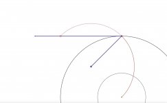
I liked the simplicity of #221 tonearm. I guess following is not 100% perfect but workable as it's guide path can be arc of circle/oval to have good geometry.
pl. Do not pay attention to crude not to scale drawing or other things. Was made to just to share the concept.
Drawing :
(A) This is cnc machine cut V groove where a ball slides in arc (Circular or oval section). Due to top plate (having same V groove) the main wand which moves forward due to stylus drag the weight does not change on swiveling pivot. There are only 4 contact points. Top curved plate is fixed to plinth or any other thing and fixing is not shown.
(B) This is swiveling+Rolling bearing. A Pivot or thread can be used. Main weight is obviously on bottom pivot. The upperpivot just needs firm contact. and can be fixed with side screw. The Horizontal bearing is again V shaped where the wheel axle will roll and has only two contact points. Again the weight of wand will not allow wheel to move out.
(C) On front of the wand There is knife edge small wand for verticle motion (For warped records)
Thinking :
My thinking was to have tight tolerance and less friction. Though at first it seems it has too many moving/bearings The knife bearing hardly will represent any friction to moving geometry. Same for the verticle ballpen pivot as its travel is small, light weight wand and is single point bearing.
The rolling wheel and the V grooved arc plates will have some friction. But as it is known the rolling objects will have less friction. The stylus drag helps in moving the wand forward in this arc section.
kindly critique.
Regards.

------------------------------------------------------------------------------------
I liked the simplicity of #221 tonearm. I guess following is not 100% perfect but workable as it's guide path can be arc of circle/oval to have good geometry.
pl. Do not pay attention to crude not to scale drawing or other things. Was made to just to share the concept.
Drawing :
(A) This is cnc machine cut V groove where a ball slides in arc (Circular or oval section). Due to top plate (having same V groove) the main wand which moves forward due to stylus drag the weight does not change on swiveling pivot. There are only 4 contact points. Top curved plate is fixed to plinth or any other thing and fixing is not shown.
(B) This is swiveling+Rolling bearing. A Pivot or thread can be used. Main weight is obviously on bottom pivot. The upperpivot just needs firm contact. and can be fixed with side screw. The Horizontal bearing is again V shaped where the wheel axle will roll and has only two contact points. Again the weight of wand will not allow wheel to move out.
(C) On front of the wand There is knife edge small wand for verticle motion (For warped records)
Thinking :
My thinking was to have tight tolerance and less friction. Though at first it seems it has too many moving/bearings The knife bearing hardly will represent any friction to moving geometry. Same for the verticle ballpen pivot as its travel is small, light weight wand and is single point bearing.
The rolling wheel and the V grooved arc plates will have some friction. But as it is known the rolling objects will have less friction. The stylus drag helps in moving the wand forward in this arc section.
kindly critique.
Regards.
Hiten,Thanks very much for the dimensions super10018.
------------------------------------------------------------------------------------
I liked the simplicity of #221 tonearm. I guess following is not 100% perfect but workable as it's guide path can be arc of circle/oval to have good geometry.
pl. Do not pay attention to crude not to scale drawing or other things. Was made to just to share the concept.
Drawing :
(A) This is cnc machine cut V groove where a ball slides in arc (Circular or oval section). Due to top plate (having same V groove) the main wand which moves forward due to stylus drag the weight does not change on swiveling pivot. There are only 4 contact points. Top curved plate is fixed to plinth or any other thing and fixing is not shown.
(B) This is swiveling+Rolling bearing. A Pivot or thread can be used. Main weight is obviously on bottom pivot. The upperpivot just needs firm contact. and can be fixed with side screw. The Horizontal bearing is again V shaped where the wheel axle will roll and has only two contact points. Again the weight of wand will not allow wheel to move out.
(C) On front of the wand There is knife edge small wand for verticle motion (For warped records)
Thinking :
My thinking was to have tight tolerance and less friction. Though at first it seems it has too many moving/bearings The knife bearing hardly will represent any friction to moving geometry. Same for the verticle ballpen pivot as its travel is small, light weight wand and is single point bearing.
The rolling wheel and the V grooved arc plates will have some friction. But as it is known the rolling objects will have less friction. The stylus drag helps in moving the wand forward in this arc section.
kindly critique.
Regards.
View attachment 1007468
It is great to see folks thinking about a workable rolling/pivot bearing to make the pivoting tangential tonearm a reality.
Your thoughts are similar to mine but with two rolling wheels side-by-side like a train wheelset to prevent sideways rocking.
https://en.wikipedia.org/wiki/Wheelset_(rail_transport)I realise that this increases complexity/friction in an already ambitious concept. Maybe there will be alternative suggestions that accomplish the same without the friction penalty.
Bon
This is a problem inherent to all magnetic rails, regardless whether one part of it is of steel or both are magnets.In my opinion, if the rail is just magnetic material, the possibility of tracking errors caused by the rail does exist because the top magnet may move sideways.
If there is a sideways force there will be a distance between the middle lines of the two parts because the magnetic force is not infinite.
When the force on the stylus exerted by the groove toward the spindle is greater than the friction force your tonearm will move backwards!Here is the mid tonearm link version. It is a much more compact guide mechanism/path with exactly the same tonearm positioning. This configuration has some favourable features. Notice all the relevant paths and pivots bar the mid-tonearm pivot, lie on the Thales circle. This is not a coincidence. Some serious geometric voodoo is at play. It will be the one I go with.
Here is another claim I have been suspecting if it is true for a while but have no definite answer for since I started to build my 6B.
The claim is that for a Birch-style arm, the primary circle can be a circle, but the secondary circle is a curve, ( I guess it is an element of Limacon). The tracking error will be zero.

I have doubts about such a claim. In order to meet the condition of zero tracking errors, the primary circle should be an element of Limacom, too. However, if the primary circle is an element of Limacom, how about the secondary circle? What will it be? I don't know. My math is not good enough to solve such problems.
For my 6B, I clearly stated that it has tracking errors because both the primary and secondary Birch circles are circles. I adjusted some of the parameters to minimize the tracking errors in order to utilize pivot bearings.
The claim is that for a Birch-style arm, the primary circle can be a circle, but the secondary circle is a curve, ( I guess it is an element of Limacon). The tracking error will be zero.
I have doubts about such a claim. In order to meet the condition of zero tracking errors, the primary circle should be an element of Limacom, too. However, if the primary circle is an element of Limacom, how about the secondary circle? What will it be? I don't know. My math is not good enough to solve such problems.
For my 6B, I clearly stated that it has tracking errors because both the primary and secondary Birch circles are circles. I adjusted some of the parameters to minimize the tracking errors in order to utilize pivot bearings.
If there is a side force, for a magnet rail, it will try to correct it. But for a non-magnet rail, there is no force to encounter the side force.This is a problem inherent to all magnetic rails, regardless whether one part of it is of steel or both are magnets.
If there is a sideways force there will be a distance between the middle lines of the two parts because the magnetic force is not infinite.
A magnet is not a PID servo control. It does not "try to correct" anything. It simply exerts a counterforce (also with a non-magnet rail) but does not diminish the error to zero.If there is a side force, for a magnet rail, it will try to correct it. But for a non-magnet rail, there is no force to encounter the side force.
Suppose the stylus is in a locked groove as shown. The only way it can move backwards in the groove is for the rear guide to jump off the track. The vectors are meaningless. Stylus forward tangential drag produces a clockwise torque about the tonearm instantaneous centre of rotation. The groove reaction will be in opposition to this torque. This claim is nonsense.When the force on the stylus exerted by the groove toward the spindle is greater than the friction force your tonearm will move backwards!
If the LP has eccentricity, all Birch-style arms or similar such as Bon's geometry will move backward. It is no big deal. When eccentricity happens, the friction force actually moves the stylus away, not toward, from the spindle. If there is no eccentricity, I don't think the arm will move backward at all. Anyway, I don't see such discussion has any significant meaning here.
Hi Jim.Here is another claim I have been suspecting if it is true for a while but have no definite answer for since I started to build my 6B.
The claim is that for a Birch-style arm, the primary circle can be a circle, but the secondary circle is a curve, ( I guess it is an element of Limacon). The tracking error will be zero.
View attachment 1007565
I have doubts about such a claim. In order to meet the condition of zero tracking errors, the primary circle should be an element of Limacom, too. However, if the primary circle is an element of Limacom, how about the secondary circle? What will it be? I don't know. My math is not good enough to solve such problems.
For my 6B, I clearly stated that it has tracking errors because both the primary and secondary Birch circles are circles. I adjusted some of the parameters to minimize the tracking errors in order to utilize pivot bearings.
I have not studied the Birch geometry at all, but I have always had concernes about claims for tangential tracking based on the usual fixed pivot circle guides. It just did not match the math. To be clear, I describe the position of the stylus on the Thales circle. Then I look to see where any other point on the tonearm is positioned as the stylus moves along the Thales circle. I discovered limacons, only a circle at the stylus end.
Here is an animation showing the paths of the tonearm link point as its position is moved from stylus towards the rear.
I chose a pivot to stylus distance of 25 cm to satisfy the requirement for larger Thales diameter for the Birch geometry.
It is clear that the tonearm path gets more distorted from a circle the further it gets from the stylus.
Can you post a link to a description of the Birch geometry you used? I would like to see for myself exactly what the original claims and justification were.
Bon
No, it is not nonsense. Your tonearm's movement is not constrained enough, it can move anywhere, not only on the Thales circle. You rely on the tangential friction to be much greater than the sum of the friction of the rails and bearings and the force exerted by the groove on the stylus.Suppose the stylus is in a locked groove as shown. The only way it can move backwards in the groove is for the rear guide to jump off the track. The vectors are meaningless. Stylus forward tangential drag produces a clockwise torque about the tonearm instantaneous centre of rotation. The groove reaction will be in opposition to this torque. This claim is nonsense.
two wheels idea is good.with two rolling wheels side-by-side like a train wheelset to prevent sideways rocking.
please see attached image. The wand is not straight arm it is with arc plate with groove at end with ball bearing. The Swiveling pivot (B) is almost never in straight line with the moving ball bearing point so it gives stability. The top arc plate (Not shown) is fixed with TT plinth. so it restricts the upward movement giving stability.
regards
The topic of this thread is quite a challenge both from the modelling perspective and probably more so from the realisation viewpoint.
Poorly considered commentary is to the detriment of the goals some of us have set. It is a needless distraction and hinders progress.
The claim that the geometry I proposed and analysed is insufficiently constrained and allows non-tangential alignment is simply refuted as follows.
As the tonearm link point is allowed to vary from the tonearm rear towards the stylus end, the circle guide path is seen to contract to eventually become a point, the centre of the Thales circle when the link point is at the stylus position. It should be clear that in this case the stylus can only lie on the Thales circle. There is no additional freedom since the guide circle is now a single point about which the link arm rotates on the Thales circle. For other link points along the tonearm the argument is slightly more subtle but the conclusion is the same.
The animation is quite useful as it can be paused to see the tangential circle guide path for each link point along the tonearm. The rear, middle, and stylus end link positions are quite interesting. Of course the guide circle must not overlap the playable area, which practically restricts the link points to the rear half of the tonearm or so.
Attachments
Labeling leads nowhere. Try to remain dispassionate.Poorly considered commentary is to the detriment of the goals some of us have set. It is a needless distraction and hinders progress.
The claim that the geometry I proposed and analysed is insufficiently constrained and allows non-tangential alignment is simply refuted as follows.
Your animation does not prove that your tonearm is sufficiently constrained.
What hinders your tonearm to be on the red or the green position? Nothing. How will you drop the stylus at the right position when you want to listen to a record?
Attachments
Here is a drawing I did to show that if the secondary Birch circle is a curve, it won't eliminate tracking errors. It does reduce the tracking errors. However, expanding the movements may be the most effective way to reduce tracking errors.Here is another claim I have been suspecting if it is true for a while but have no definite answer for since I started to build my 6B.
The claim is that for a Birch-style arm, the primary circle can be a circle, but the secondary circle is a curve, ( I guess it is an element of Limacon). The tracking error will be zero.
View attachment 1007565
I have doubts about such a claim. In order to meet the condition of zero tracking errors, the primary circle should be an element of Limacom, too. However, if the primary circle is an element of Limacom, how about the secondary circle? What will it be? I don't know. My math is not good enough to solve such problems.
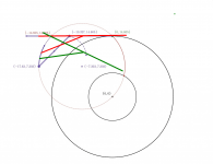
The red and green positions don't exist. The issue with this geometry is its complicated construction.Labeling leads nowhere. Try to remain dispassionate.
Your animation does not prove that your tonearm is sufficiently constrained.
What hinders your tonearm to be on the red or the green position? Nothing. How will you drop the stylus at the right position when you want to listen to a record?
View attachment 1008274
A very concise and convincing argumentation.The red and green positions don't exist.
The drawing you did was wrong. Both red and green instances in your drawing don't exist in Bon's geometry. You drew wrong conclusion from an inaccurate drawing. The drawing below is a correct one. All three X's (black, red, green) should be equal. All three Y's (black, red, green) should be equal.A very concise and convincing argumentation.
Last edited:
- Home
- Source & Line
- Analogue Source
- A tangential tracking pivoting tonearm