On another thread I proposed several sophisticated RIAA preamps, adding LTSpice simulations for all or most of them.
One of the main problems in simulating RIAA preamps in any program is that you have to add a load that includes both the anti-RIAA and the cartridge.
The one I found the most interesting one was an opamp representation of an idea Erno Borbely had proposed years ago in The Audio Amateur magazine, in a discrete preamp design e introduced there.
The RIAA part of the preamp was split in two preamps: the first one being passive and the second being active.
So with the help of some DIYAudio friends, which I hope show themselves here, it was arrived to working preamps with excellent simulation specs.
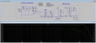
To start showing models and sims, I will start by what I consider a brilliant development by Hans Polak to the original proposal by EB.
It is to be noted that also MarcelvrdG contributed to this design.
One of the main problems in simulating RIAA preamps in any program is that you have to add a load that includes both the anti-RIAA and the cartridge.
The one I found the most interesting one was an opamp representation of an idea Erno Borbely had proposed years ago in The Audio Amateur magazine, in a discrete preamp design e introduced there.
The RIAA part of the preamp was split in two preamps: the first one being passive and the second being active.
So with the help of some DIYAudio friends, which I hope show themselves here, it was arrived to working preamps with excellent simulation specs.
To start showing models and sims, I will start by what I consider a brilliant development by Hans Polak to the original proposal by EB.
It is to be noted that also MarcelvrdG contributed to this design.
Attachments
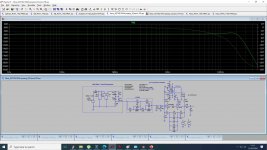
Second example for same cartridge and anti-RIAA load, in this case into a preamp originally suggested by LT, with an LT115 at the input, then used by Adcom on one of their preamps, no made anymore.
Gary Galo modified this ADcom preamp, substituting the first stage with and AD745, mod suggested by Walt Jung.
It's interesting to note that in this case, different from the other preamp the original preamp input load (47k + 100pF) was kept.
As usual, the asc file is included for anyone interested in checking on this simulation.
Hans and Marcel loads are feeding the input.
Attachments
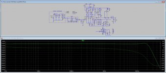
Third example using Hans and Marcel load, this time into a Luxman 5C50 discrete preamp from the '80s.
I can't call this design a "clone" because none of the active parts are like the original, so what I'm basically using is the architecture.
The original design was "pure DC", which for a DIYer is practically impossible to achieve, particularly nowadays and using through hole parts as I should be using. My guess is it would be more difficult to do using SMD parts, at least for the active parts. Imagine someone soldering and desoldering SMD transistors in order to mate them.
So my suggestion for this design, and the way I will most probably use, is made the pcb design with a DC servo that I can disconnect and add a large non-polar design on the feedback that I can bypass.
What seems to affect the FR more is the load capacitor, if if exceeds 47K.
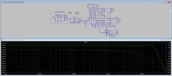
Enclosed are the responses with and without DC Servo.
Soon I will add the THD responses, along with the asc files to get them.
Let's hope Hans and Marcel are around to comment on these results I'm getting.
I can't call this design a "clone" because none of the active parts are like the original, so what I'm basically using is the architecture.
The original design was "pure DC", which for a DIYer is practically impossible to achieve, particularly nowadays and using through hole parts as I should be using. My guess is it would be more difficult to do using SMD parts, at least for the active parts. Imagine someone soldering and desoldering SMD transistors in order to mate them.
So my suggestion for this design, and the way I will most probably use, is made the pcb design with a DC servo that I can disconnect and add a large non-polar design on the feedback that I can bypass.
What seems to affect the FR more is the load capacitor, if if exceeds 47K.
Enclosed are the responses with and without DC Servo.
Soon I will add the THD responses, along with the asc files to get them.
Let's hope Hans and Marcel are around to comment on these results I'm getting.
Attachments
Hi EDDELARUE
regarding the White Cathode Follower from which the Push Pull Emitter Follower was derived, does the WCF also have improved distortion figures vs a simple CF?
https://www.epanorama.net/sff/Misc/Emitter-Followers
regarding the White Cathode Follower from which the Push Pull Emitter Follower was derived, does the WCF also have improved distortion figures vs a simple CF?
https://www.epanorama.net/sff/Misc/Emitter-Followers
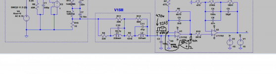
The circuit from Hans in post #1 of this thread has some big advantages and two disadvantages, one of which is no problem for you and one of which can be solved:
1. It has a better frequency response than the conventional solutions
2. It has a better transient response than the conventional solutions
3. It is less sensitive to the cable capacitance than the conventional solutions
4. It only works properly with Shure V15-III cartridges
5. It generates more thermal noise than the conventional solutions
The first three points are advantages and point 4 is not an issue for you, since you wanted to use a Shure V15-III anyway. That leaves point 5. I haven't calculated yet if it is bad enough to cause a noticeable increase of noise while playing a record or if it only makes a difference in between records.
In the first case, it could be solved with something like the attached circuit, which has a so-called cold input resistance realized with mixed series and shunt feedback. It's a technique that dates back to 1939 and that is used all over the place for RF LNA design, but it has never become popular in audio.
Edit: I made a silly mistake, that 52.3 kohm // 220 pF should be 57.6 kohm // 206 pF (which can be made with 150 pF and 56 pF in parallel).
Attachments
Last edited:
I think it is not entirely useless to use a cold resistance, even if you don't care about the noise in between records. I estimate the noise due to the low termination resistor to be about 1.16 uV RIAA- and A-weighted. The sensitivity of the cartridge is only 3.5 mV at 5 cm/s according to https://www.shure.eu/productdocumen...serguide-74e6330437db0e04da83963aa33d3e58.pdf
That leads to a 69.57 dB(A) signal to noise ratio (relative to 5 cm/s, 1 kHz) if the termination resistor were the only noise source. According to measurements of a Japanese forum member with a complicated user name (starting with xx3st or so), good records have about 60 dB(A) signal to noise ratio relative to 5 cm/s, 1 kHz, so probably record surface noise still dominates, but if your records are a bit quieter than his that may not be true anymore. When they are the same, you still lose about 0.45 dB due to termination resistor noise when you don't use a cold resistance.
That leads to a 69.57 dB(A) signal to noise ratio (relative to 5 cm/s, 1 kHz) if the termination resistor were the only noise source. According to measurements of a Japanese forum member with a complicated user name (starting with xx3st or so), good records have about 60 dB(A) signal to noise ratio relative to 5 cm/s, 1 kHz, so probably record surface noise still dominates, but if your records are a bit quieter than his that may not be true anymore. When they are the same, you still lose about 0.45 dB due to termination resistor noise when you don't use a cold resistance.
Last edited:
Hi EDDELARUE
regarding the White Cathode Follower from which the Push Pull Emitter Follower was derived, does the WCF also have improved distortion figures vs a simple CF?
https://www.epanorama.net/sff/Misc/Emitter-Followers
H Freddi,
regarding triodes, I'm sorry. I don't know. But I believe yes.
Marcel,
Regarding point 4 you are mistaken: I don't have a Shure V15 and won't be using one.
Mine is a Joseph Grado Signature, but I have to find the metal cylinder it came in to tell the exact model. I remember that at the time, probably 30 years ago, it costed me $200 in the USA and it was highly recommended.
Carl: If you have a Grado that changes the reference for you. Grados are insanely low impedance for an MM so many of the problems that can occur with loading on other MMs it is immune to. In return you get a whole new set of problems ") .
.
@Marcel: I sometimes feel guilty that I have on the desk MM stages that only really work with one cartridge, but that is half the fun when you are in charge of your own folly!
.@Marcel: I sometimes feel guilty that I have on the desk MM stages that only really work with one cartridge, but that is half the fun when you are in charge of your own folly!
The circuit from Hans in post #1 of this thread has some big advantages and two disadvantages, one of which is no problem for you and one of which can be solved:
1. It has a better frequency response than the conventional solutions
2. It has a better transient response than the conventional solutions
3. It is less sensitive to the cable capacitance than the conventional solutions
4. It only works properly with Shure V15-III cartridges
5. It generates more thermal noise than the conventional solutions
The first three points are advantages and point 4 is not an issue for you, since you wanted to use a Shure V15-III anyway. That leaves point 5. I haven't calculated yet if it is bad enough to cause a noticeable increase of noise while playing a record or if it only makes a difference in between records.
In the first case, it could be solved with something like the attached circuit, which has a so-called cold input resistance realized with mixed series and shunt feedback. It's a technique that dates back to 1939 and that is used all over the place for RF LNA design, but it has never become popular in audio.
Edit: I made a silly mistake, that 52.3 kohm // 220 pF should be 57.6 kohm // 206 pF (which can be made with 150 pF and 56 pF in parallel).
Very interesting I own a Shure V15-III original, please could you post the full schematic, thanks in advance?
Last edited:
The circuit from Hans in post #1 of this thread has some big advantages and two disadvantages, one of which is no problem for you and one of which can be solved:
1. It has a better frequency response than the conventional solutions
2. It has a better transient response than the conventional solutions
3. It is less sensitive to the cable capacitance than the conventional solutions
4. It only works properly with Shure V15-III cartridges
5. It generates more thermal noise than the conventional solutions
The first three points are advantages and point 4 is not an issue for you, since you wanted to use a Shure V15-III anyway. That leaves point 5. I haven't calculated yet if it is bad enough to cause a noticeable increase of noise while playing a record or if it only makes a difference in between records.
In the first case, it could be solved with something like the attached circuit, which has a so-called cold input resistance realized with mixed series and shunt feedback. It's a technique that dates back to 1939 and that is used all over the place for RF LNA design, but it has never become popular in audio.
Edit: I made a silly mistake, that 52.3 kohm // 220 pF should be 57.6 kohm // 206 pF (which can be made with 150 pF and 56 pF in parallel).
Marcel, I'm very glad you came by. Now let's hope Hans gets interested too.
Which opamp should I use to do that you suggest? I would like to simulate it.
Pity I do not have the necessary instruments to measure this preamp, because the simulation results are great.
Also I wonder if the DC offset results will be as low as the sim shows, or if a simple output cap would block it with minimum audible cap distortion.
You were the one that warned me, very properly, against what a DC servo might cause on a RIAA preamp. Borbely did use them, but he knew what he was doing. The Gary Galo mod to the LT/Adcom preamp also used a servo, but they also knew what they were doing. I do not.
OTOS, do you think is valid or useful to add a DC servo to a high offset (>30mV?) preamp and listen to how it affects the sound?
The "I'm" is assumed, as in "I'm curious what you think of my version." I don't see huge differences in performance between very simple and very complex circuits, other than the gain limitations of the common 2-transistor circuits used in many receivers. I'd think almost all opamp implementations should do well, but I keep the gain low on the first stage and use a different feedback arrangement on the second. Have I given away some performance that I shouldn't have?
- Status
- This old topic is closed. If you want to reopen this topic, contact a moderator using the "Report Post" button.
- Home
- Source & Line
- Analogue Source
- RIAA preamps versus real loads