Lets see now,the IRF820 seems to be fine it outputs about 250v,there is 250v at one end of the resistor but (R9p) not at the other side.''
And theres no shortcut ,to ground at the resistor,
But the kathode of ZD3R and L is shortcuted to ground should it be so??
The filament regulator seems to not broken it has 14v in and 10v out but the ground is about 4,5v above ground,theres 4,5v att the zener.
Can I try with a red led?
And theres no shortcut ,to ground at the resistor,
But the kathode of ZD3R and L is shortcuted to ground should it be so??
The filament regulator seems to not broken it has 14v in and 10v out but the ground is about 4,5v above ground,theres 4,5v att the zener.
Can I try with a red led?
Lets see now,the IRF820 seems to be fine it outputs about 250v,there is 250v at one end of the resistor but (R9p) not at the other side.''
And theres no shortcut ,to ground at the resistor,
But the kathode of ZD3R and L is shortcuted to ground should it be so??
The filament regulator seems to not broken it has 14v in and 10v out but the ground is about 4,5v above ground,theres 4,5v att the zener.
Can I try with a red led?
The filament regulator (7805) should be giving 7 volts out with the zener or a 2v LED between the centre pin and ground, not 10v.
Not sure about that, I know R1P is part of that particular circuit, but not really sure what it does.
Again Vivant is the best man to ask.
Re the HT & LT ground, I would again check with Vivant. I was under the impression that both circuits are totally isolated from each other, but I certainly may be wrong.
Again Vivant is the best man to ask.
Re the HT & LT ground, I would again check with Vivant. I was under the impression that both circuits are totally isolated from each other, but I certainly may be wrong.
Last edited:
Cathode of ZD3R and L are connected to ground, that is correct.
R1P (4.7K) provides extra current through ZD1P, or red LED. You should get about 7V from the LV regulator when correct.
HV and LV grounds are separate, do not connect together. The LV ground is raised by about 55V to match heater/cathode ratings.
Measure across C7P or C8P to make sure there are no HV shorts.
After a chance conversation in a supermarket queue about minimum order quantities and punitive postage I got offered a bunch of Zener diodes for the price of a coffee ")
Included among them were 2.0 and 2.4v
LT ac is 20.8 across taps.
HT ac is 187 across taps.
No valves in place for any of the measurements.
With a 2.4v zd1 I get 6.95v on pin 4 of v1,2,3 with slightly over 13v as input to the vreg.
So I connected the HT as well. Jumper set for ECC83. And got:
Minuses mean low mv, just not quite zero.
Does this look reasonable & safe to plug the valves in and push a signal through?
Included among them were 2.0 and 2.4v
LT ac is 20.8 across taps.
HT ac is 187 across taps.
No valves in place for any of the measurements.
With a 2.4v zd1 I get 6.95v on pin 4 of v1,2,3 with slightly over 13v as input to the vreg.
So I connected the HT as well. Jumper set for ECC83. And got:
Code:
143.6, ----, -0.9, 66.7, 59.7, 143.8, ----, -0.9,  0.0
159.6, ----,  0.0, 66.7, 66.7, 159.7, ----, ----, 59.5
250.1, 18.1, 17.5, 66.6, 59.7, 250.9, 18.1, 17.5, 0.0Does this look reasonable & safe to plug the valves in and push a signal through?
Valves in, mm/mc leds lit voltages still look good. Hooked up to amp and.... silence. Hasty checking of what's soldered to what cable wise, <expletives deleted>, back to amp and yaaaay music. First impressions are completely positive but I really need to sit down with it boxed up for a proper listening session to get the full picture.
So some cleaning up and changing RIAA & JFet resistors and case to assemble, then done.
Thankyou everyone, for BB, for the help and advice.
A couple of questions:
1. How long does BB need to 'warm up'? I'm guessing a couple of minutes for everything to warm to operating temperature. But is that so?
2. Is there a 'burn in' time before I see the best of BB? I've already burnt in the clarity caps, but for the rest of the amp?
Changing RIAA resistors? Type or tolerance rather than stated value in the BOM I hope!Valves in, mm/mc leds lit voltages still look good. Hooked up to amp and.... silence. Hasty checking of what's soldered to what cable wise, <expletives deleted>, back to amp and yaaaay music. First impressions are completely positive but I really need to sit down with it boxed up for a proper listening session to get the full picture.
So some cleaning up and changing RIAA & JFet resistors and case to assemble, then done.
Thankyou everyone, for BB, for the help and advice.
A couple of questions:
1. How long does BB need to 'warm up'? I'm guessing a couple of minutes for everything to warm to operating temperature. But is that so?
2. Is there a 'burn in' time before I see the best of BB? I've already burnt in the clarity caps, but for the rest of the amp?
Well done for getting there [emoji4]
About 20mins to come on song and I alway recommend 50hrs minimum for burn in, and yes it is real!!
If you use the MultiFET boards with the newer Jfets (yes they changed too due to becoming obsolete) then R11P will need changing from 330k to 390k, which lowers noise significantly.
We also built an extremely accurate inverse RIAA network and found a tiny overshoot in the HF end of the RIaa equalisation.
This was fixed by changing R10L&R from 68k to 71k.
Those. 330k 68k(0.1%) were in my BOM and I might as well get the correct values in place to squeeze the last out of the orange. All well matched of course.
I used to have a lw/sw/mw valve radio/record player that took around 20mins to hit a good operating temperature. It was an excellent winter footwarmer. Not sure I can try the same with BB.
It's been an interesting weekend listening to BB as it burns in. Initially too much top end and harsh too with, weirdly, a big emphasis on LP surface noise.
But as the hours go up, the harshness has faded as has the surface noise and I think in another couple of days it'll have settled nicely. Already an improvement on anything I've got in the house. Using Ortofon 2M Black.
Top end looking nice, bass tight, controlled and there when it needs to be, midrange detailed. Imaging is special, everything in place and with width, depth and space.
Sibilance. Which I hate. BB has really good control of it.
Chuffed as nuts.
Thanks guys.
The Zener debate:
When Alan and I did the original BOM, we used a Phillips data's sheet to reference the correct heater voltage for the 2x PCC88
The data sheet clearly stated that the phillips PCC88 was 7.2v
However, we later discovered that almost every other PCC88 is 7v.
We changed the BOM to reflect this and the value fitted now is a 2v Zener.
I did post a link to the BOM on a thread here, which I thought was this one but I cant find it now, so I will repost a link later today.
If you use the MultiFET boards with the newer Jfets (yes they changed too due to becoming obsolete) then R11P will need changing from 330k to 390k, which lowers noise significantly.
We also built an extremely accurate inverse RIAA network and found a tiny overshoot in the HF end of the RIaa equalisation.
This was fixed by changing R10L&R from 68k to 71k.
You need to buy 1% 71.5k resistors and find the closest value, or make them out of two resistors in series.
Tried 0.1% 69.8k and they were close enough if you want an easy life [emoji6]
All of these little changes made improvements, so don't be afraid to adopt them.
Ollie
I've lost track here, you supplied me two MultiFET boards at the end of December/beginning of January this year.
Which resisters should I have in R11P? I've got 330k at the moment.
Do I need to change to 390k?
Damn, now I've got a question. Do you mean there are different multifet boards? If so, how can I tell which boards I have? They're boards you sent me in November to replace the one I managed to bork.
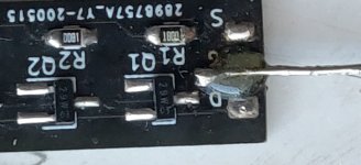
Incidentally, I managed to solder a line to the remains of the pad. It flapped around a bit, so I secured it with some Araldite. It appears I managed to get the electrical connection OK and measures the same resistances as the unbroken one.
But I've not had the courage to actually try it...
Incidentally, I managed to solder a line to the remains of the pad. It flapped around a bit, so I secured it with some Araldite. It appears I managed to get the electrical connection OK and measures the same resistances as the unbroken one.
But I've not had the courage to actually try it...
Attachments
No, they are the original ones.Damn, now I've got a question. Do you mean there are different multifet boards? If so, how can I tell which boards I have? They're boards you sent me in November to replace the one I managed to bork.
Incidentally, I managed to solder a line to the remains of the pad. It flapped around a bit, so I secured it with some Araldite. It appears I managed to get the electrical connection OK and measures the same resistances as the unbroken one.
But I've not had the courage to actually try it...
330k is fine.
- Home
- Source & Line
- Analogue Source
- Bigbottle Phonostage Builders thread.