Gerhard, Interesting observation. There are two different circuits being used here, a variation on Richard Lee's design and one based on a John Curl design. An example of the first design with ca. -30dB/dec is Syn08's realisation, see here. htps://www.diyaudio.com/forums/analogue-source/339246-richard-lees-ultra-low-noise-mc-head-amp-post5842585.html.
An example of the second design with ca -30dB/dec is two pages back in posting #1504. This one, the transimpedance version, has ZTX transistors with a high LF knee frequency. The Voltage amp however, using the same amp module, happened to have ZTX transistors with much lower knee frequencies, making the -30dB/dec LF noise drown into the flat noise. See also posting #1517 what spread there is in the knee frequency between these ZTX transistors.
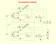
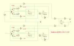
And yes, what is drawn as an amp is of course not an op-amp, but as mentioned a circuit based upon John Curl's original 2 transistor patented MC circuit. See below for the transimpedance version. Supply voltage is -1.5V / +2.1V, causing an Ic of 3.1mA through the transistors,
Hans
P.S. All 3.9mF in Syn08's and my version are the Nichicon 2.5V polymer caps, type PLG0E392MDO1 .
An example of the second design with ca -30dB/dec is two pages back in posting #1504. This one, the transimpedance version, has ZTX transistors with a high LF knee frequency. The Voltage amp however, using the same amp module, happened to have ZTX transistors with much lower knee frequencies, making the -30dB/dec LF noise drown into the flat noise. See also posting #1517 what spread there is in the knee frequency between these ZTX transistors.
And yes, what is drawn as an amp is of course not an op-amp, but as mentioned a circuit based upon John Curl's original 2 transistor patented MC circuit. See below for the transimpedance version. Supply voltage is -1.5V / +2.1V, causing an Ic of 3.1mA through the transistors,
Hans
P.S. All 3.9mF in Syn08's and my version are the Nichicon 2.5V polymer caps, type PLG0E392MDO1 .
Attachments
Last edited:
Thanks!
I still have no idea where these 30 dB/decade come from. Even telegraph noise (catching/releasing carriers) is only 1/f. < https://www.nii.ac.jp/qis/first-quantum/forStudents/lecture/pdf/noise/chapter9.pdf >
For 30 dB/decade, I guestimate that some energy collection must take place: the longer the events are apart, the higher is their amplitude. Much like earthquakes: the longer we have to wait for the big one in SF, the worse it will be.
But collecting energy is a typical capacitor thing, I can't think of such an effect in a semiconductor junction, more than maybe the plasma blobs in an Avalanche diode (not a true Zener).
But that is just some speculation from my side.
Cheers! (lifting a cup of fennel tea) Gerhard
PS Maybe one should swap parts to see if the effect wanders with the part.
Last edited:
Great thread, just stumbled upon it! Are you just doing simulations, or do these circuits actually get built and listened to?
Seems to me there is a lot more to good MC headamp design than just low noise. How low do you need to go anyway? As far as I'm concerned, as long as the electronic's noise floor is well below groove noise, you're in a happy spot. And the "Huygens" (with its monstrous 3nV) does so handily.
I'm glad you covered headroom, because that's also super important; as is the ability to recover from pops and tics (no NFB). Linearity must shine at high signal levels. And let's not forget power supply noise injection with a practical implementation. Layout? Susceptibility to hum? Thermal effects? Output drive? Input bias current being pulled through the coils of a cartridge?
I didn't get through all 150 pages here, but was wondering if anyone did listening tests?
jh
I'm about to start listening next week, because I'm very interested to hear if any difference can be perceived between a Transimpedance and a Voltage amp.
There are a lot of different opinions about transimpedance amps lately, from overwhelming, to not suitable for every MC Cart or to even no difference at all between the two. So that was my main intention.
Hans
There are a lot of different opinions about transimpedance amps lately, from overwhelming, to not suitable for every MC Cart or to even no difference at all between the two. So that was my main intention.
Hans
I have tested 10 ZTX951's, took the best of them and tested 10 ZTX851's. With the ZTX 951 there where still difference visible, although not very much, but with the 10 ZTX851's there where no differences at all !! I could not even come close to the LF noise spectrum of the other half of the transimpedance amp.
That's why I think that Gerhard may have suggested a useful tip, that the LF noise might be caused by the 3.9mF Nichicon caps. So I'm going to replace them and see what happens.
Hans
That's why I think that Gerhard may have suggested a useful tip, that the LF noise might be caused by the 3.9mF Nichicon caps. So I'm going to replace them and see what happens.
Hans
I have tested 10 ZTX951's, took the best of them and tested 10 ZTX851's.
How did you test them?
Is there somewhere a better schematic drawing? I am having troubles following what is posted above, and I am too lazy to re-draw myself.
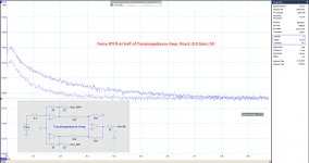
Here is a complete schematic drawing of the used differential transimpedance amp. Upper half has a gain of 50 and lower half a gain of 1. The 0.5R resistor at the input can also be moved to the lower part, to give the upper half a gain of 1 and the lower half a gain of 50. Noise from the output should be the same in both cases, but the measured LF noise differed very much, see posting #1517.
I replaced both transistors in the noisy upper half by a socket, so I could easily replace transistors without soldering. The result as mentioned in #1526 was disappointing .
Hans .
I replaced both transistors in the noisy upper half by a socket, so I could easily replace transistors without soldering. The result as mentioned in #1526 was disappointing .
Hans .
Attachments
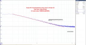
Correct, #1508 doesn't show the 30dB/decade, this is the better behaving Voltage Amp, where the -30dB/dec is probably submerged in the flat noise and therefore invisible. But the much worse Transimpedance Amp has the ca 30dB/dec clearly visible, see image below, here measured with both halves having the full gain of 50. That was the reason why I started to test the separate halves, to find out that only one half was to blame for the high LF noise.
More and more the thought forces to my mind that the ZTX transistors are probably not at all responsible for the LF noise, but that the Nichicons are to blame. That would explain why Wayne with ZTZ851's and no caps at all measures a flat noise spectrum up to 20 Hz. See the middle imgage here: Richard Lee's Ultra low Noise MC Head Amp
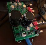
Unfortunately I have no spare caps to exchange, but tomorrow I will finalise a second Transimpedance board, with caps already mounted.
Hans .
More and more the thought forces to my mind that the ZTX transistors are probably not at all responsible for the LF noise, but that the Nichicons are to blame. That would explain why Wayne with ZTZ851's and no caps at all measures a flat noise spectrum up to 20 Hz. See the middle imgage here: Richard Lee's Ultra low Noise MC Head Amp
Unfortunately I have no spare caps to exchange, but tomorrow I will finalise a second Transimpedance board, with caps already mounted.
Hans .
Attachments
But the writing was already on the wall since #705, #708
The "somewhat better" cap I had on order was also not completely effect-free, but still better than the poly cap that gave me the full broadside. And it was 20 or 25 Volts and high temp. So it is probably a matter of luck unless you follow Jim Williams of LT and use wet slug tantalums that cost 100 Bucks for 4700u/25 .
The Design with the feedback-free input stage is now nearly done; the input fets are climatized at 35°C to avoid the 0.8 dB/10°C gain error b/c of the missing feedback. The digital stuff only converts gain switches to analog switch controls for 40/50/60/70 dB gain, +0, +3, +6, +9 dB fine gain and lopass corners from 100 Hz to 1 MHz and it provides opto-isolated SPI for computer control.
I use +16/-8V from Lithium batteries. They are definitely clean.
Attachments
Last edited:
Powering from batteries or mains makes no measurable difference.I would be very surprised to be the caps. I’ve built 6 or 8 boards of #375 and didn’t have any problems with these. OTOH I can’t explain this huge slope based on transistors only, very strange. Is the same when powering from batteries?
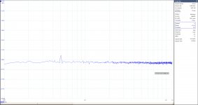
But I left the Head amp under power the whole night. Noise in the good half stayed the same, but went down by more then 10dB in the other bad half, see image below. Could it be that the caps needs some forming ?? However, since there is still 10dB difference in LF noise between both halves, I will see what I can do in replacing the caps.
Hans .
Attachments
I always love this comment from that app note
Note 1. This high yield is most welcome because the specifi ed capacitors are spectacularly priced at almost $400.00. There may be a more palatable alternative. Selected commercial grade aluminum electrolytics can approach the required DC leakage although their aperiodic noise bursts (mechanism not understood; reader comments invited) are a concern.
Powering from batteries or mains makes no measurable difference.
But I left the Head amp under power the whole night. Noise in the good half stayed the same, but went down by more then 10dB in the other bad half, see image below. Could it be that the caps needs some forming ?? However, since there is still 10dB difference in LF noise between both halves, I will see what I can do in replacing the caps.
It get weirder and weirder. Could you check your measurement setup by replacing the amp with a known resistor? Then the noise drift should not appear.
To my experience, the Nichicon capacitors are excellent. See all the noise measurements I posted in this thread. Perhaps I was lucky or you had bad luck.How much more prove do we need that the Nichicons are bad news.
See image below with two 35Volt 4.7mF alu caps. And this is with the transistors that where originally soldered on the PCB. What a difference !
Hans
Indeed big difference. I don't understand your last noise measurement, I see no 1/f noise at all. That's a physical impossibility. Unless the noise corner frequency is much under 10Hz, which I would find very hard to believe. I have never seen a discrete bipolar with such a low corner noise frequency. Some ICs (LT1028) are claiming a typical value under 5-10Hz noise corner frequency, but even such low should be visible on your plot. AD797 seem to have about 50Hz for voltage noise and about 100Hz for the current noise, according to the data sheet. OPA211 has about 20Hz according to the data sheet, and that's a SiGe device.
P.S. You could easily set up a measurement jig for these caps, biased @3V. That's probably too much to ask, I'll do it myself when I'll have the time.
Last edited:
When we have a 1/f corner at 10 Hz and a -3 dB corner at 10 Hz(after the input stage), then we should see a slight decrease below that frequency. The plot would support that. There are bipolar op amps with 1/f corners lower than 10 Hz.Indeed big difference. I don't understand your last noise measurement, I see no 1/f noise at all. That's a physical impossibility.
The ugly side is that my cheap Rubycon capacitors are OK now, but will they still be OK next year?
- Home
- Source & Line
- Analogue Source
- Richard Lee's Ultra low Noise MC Head Amp