I hear you Richard. The "problem" really is that one TT set-up runs fine at 40 out of 63 "steps" on the attenuator but the other TT with less of a cartridge output (0.3 vs 0.4mV) and the Emerald PS, needs me to increase the volume to 45/63 steps. I just would like them to be a little more balanced that is all.
Since I socketed all those resistor sockets, it is an easy 5 minute switcheroo.
Since I socketed all those resistor sockets, it is an easy 5 minute switcheroo.
edit to my previous post - MC gain is 55-60 dB, not 35-40dB, and the max cap I'd suggest is 65 dB.
Anyway, if you just want to normalize the gain between analog front ends, not problem: just tweak R3 to however much gain those extra 5 steps on the volume control amount to. I imagine its about 5 dB. With sockets, you can just try a few values until you find the one that matches.
Anyway, if you just want to normalize the gain between analog front ends, not problem: just tweak R3 to however much gain those extra 5 steps on the volume control amount to. I imagine its about 5 dB. With sockets, you can just try a few values until you find the one that matches.
Picking up a Hana EL this week, spec sheet lists 0.5mV output and a suggested load impedance >400ohms, I don’t have the switchboard on my emerald so am I correct in assuming I would just choose something like a pair of resistors in the 470-1k range and swap those out with the 100’s and then use the jumper to parallel the new resistors with the 47k? Cart doesn’t list capacitance it prefers either.
Yes, you'd switch out the 100 ohm resistors for something around 400- ohms.
or, if you dont want to mess with desoldering you can set the jumper to the 47k ohms position (MM) and solder the 400 ohm resistors at the RCA jacks.
or, if you dont want to mess with desoldering you can set the jumper to the 47k ohms position (MM) and solder the 400 ohm resistors at the RCA jacks.
Thanks for the quick reply, turns out my compromised single enclosure “everything jammed way too close together but it’s what I have to work with” solution worked fine for MM but introduced some noise when I swapped over to MC. Separate enclosures are on the way from Ali express for a more permanent solution but this janky fix to get the boards further from the rectifiers and toroid has gotten that noise from “legitimately annoying” to “barely audible” and will totally hold me over for a month while I wait for the other enclosures to show up.
Attachments

The diode can radiate out noise which is picked up by the big coupling caps, so moving the caps away from the diodes (and transformer, and AC wiring) should fix things.
Also, those black anodized cases are notorious for having bad electrical contact between the various metal pieces. Some sections can therefore end up disconnected from the earth unless you are careful to scrape off the anodized material at the joins.
Also, those black anodized cases are notorious for having bad electrical contact between the various metal pieces. Some sections can therefore end up disconnected from the earth unless you are careful to scrape off the anodized material at the joins.
You’re absolutely right about the anodized coating, I thought I was pretty thorough with my scraping and when I was trying to figure out this buzz I found two things that should have been grounded that were showing like 500ohms to ground.The diode can radiate out noise which is picked up by the big coupling caps, so moving the caps away from the diodes (and transformer, and AC wiring) should fix things.
Also, those black anodized cases are notorious for having bad electrical contact between the various metal pieces. Some sections can therefore end up disconnected from the earth unless you are careful to scrape off the anodized material at the joins.
its basically just going to look like a weird science experiment until my pair of new enclosures arrive but I kinda dig the aesthetic for now.
Hey Richard,
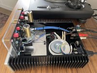
I'm looking to build my first Emerald stage and wanted to build it similar to the one you built in this picture. I'm going to build the power supply and phono stages into separate housings.
I understand that you prefer to use solid core twisted pair cable from ethernet / LAN cable for the signal connections.
Can you tell me what cable you are using for the DC connections?
Do I have to use anything special for the DC interconnect cable or do most people just use 3 core mains cable?
I look forward to getting started!
Thanks
Dave
Hello Richard,
I am missing somthing. Maybe you can shine your light on it.
I am powering the Emeralds dual mono, 2x DBRB and two transformers.
The transformers are 2x15vac 2x1.67amp (for 15vdc). The resistor 20-21 = 12k. I get (-)21.45 on V-- and V++, But on ref. i get +/-0.0500v. I did also tried 11k on 20-21.
What am i missing here?
To reply to the above,
1. I use unsheilded 3-wire AC cable for the umbilical, with an XLR connector at the phono stage side, and the power supply side hardwired.
2. V+ should be 9-13 V range, and yes, using 22k instead of 22 ohms would disable the S-reg circuit and cause V+ and V- to both fall to zero.
Richard
1. I use unsheilded 3-wire AC cable for the umbilical, with an XLR connector at the phono stage side, and the power supply side hardwired.
2. V+ should be 9-13 V range, and yes, using 22k instead of 22 ohms would disable the S-reg circuit and cause V+ and V- to both fall to zero.
Richard
Hello Richard,
I have build the two Emerald phono amps. Everyone has their own preferences regarding used parts and setup. I use the Emerald only for MM. I use a 15volt setup because in my experience this sounds better with the op amps i use (Signetics 5534). I also have a dual mono setup and i use matched original Philips bd139-bd140.
I wanted to let you know that your Emerald is in my opinion the best op amp based phono around! I can not see one point where it can be improved. It can be made more complex but a simple wel balanced circuit + good psu is king imho. And that's wat the Emerald is about.
This phono is my op amp phono end game! Thanks for your efforts.

Hi Richard,
The cartridge I'm using calls for an input load of 10K to 47K Ohms.
Right now, I have the stock 47.5K resistor on my board.
Would I benefit from lowering this to a smaller value, to put it in the middle of the cartridge's range?
Thanks!
David
The cartridge I'm using calls for an input load of 10K to 47K Ohms.
Right now, I have the stock 47.5K resistor on my board.
Would I benefit from lowering this to a smaller value, to put it in the middle of the cartridge's range?
Thanks!
David
Hi David,
I think that's just the manufacturer's way of telling you that the load resistance doesn't really matter as long as it is above 10k.
It might change the character of the sound slightly, but there is no right or wrong here, and no reason to imaging that the middle value would be better. It's just 10k and 47k are standard loads you tend to see, and they are saying either one is fine.
/R
Thanks Richard!
My Emerald actually sounds great as is. No problems. I just saw that specification and it got we wondering.
But, your explanation makes total sense. I can see why a cartridge manufacturer would state a usable range like that.
David
My Emerald actually sounds great as is. No problems. I just saw that specification and it got we wondering.
But, your explanation makes total sense. I can see why a cartridge manufacturer would state a usable range like that.
David
Hi everybody ...
I´ll start to build my second Emerald phono and I´m little confused right now ... My first build contains OPA27GP Burr Brown ... This opamp is out stock for now ... RJM audio parts list says: OPA134 or OP27, OP27 is still available ... OP27 is produced by Analog Devices. but where´s the main difference between OP27 and OPA27 ? Thank´s 🙂
I´ll start to build my second Emerald phono and I´m little confused right now ... My first build contains OPA27GP Burr Brown ... This opamp is out stock for now ... RJM audio parts list says: OPA134 or OP27, OP27 is still available ... OP27 is produced by Analog Devices. but where´s the main difference between OP27 and OPA27 ? Thank´s 🙂
The main difference is the OPA27 is a Burr Brown / TI product, while the OP27 is the Analog Devices equivalent.
I don't know if they are exactly the same circuit, but they are very similar and designed to be functionally compatible.
I don't know if they are exactly the same circuit, but they are very similar and designed to be functionally compatible.

- Home
- Source & Line
- Analogue Source
- RJM Audio Emerald Phono Stage Help Desk