Hello all,
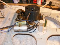
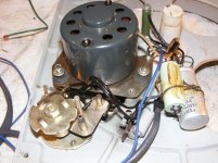
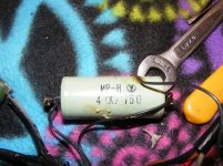
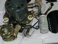
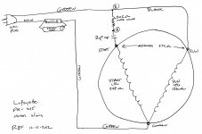
Expert electrician I am not. I am trying to refurbish this table and from pictures on the web and visual appearance I can see that someone has added a capacitor to the table. I can't find a schematic or service manual anywhere. I have attached pictures of the table with the piggybacked capacitor and also one from the web in original condition. I also drew a crude wiring diagram. The picture of the MP-H 4 (K) 150 shows the capacitor that was added. Any enlightenment as to why the capacitor was added, and what value/voltage, would be greatly appreciated. Also if someone could explain the purpose of three connections on the original capacitor. I thought there were three connections only if it was a dual capacitor internally. Is it a combined start/run capacitor? Thanks in advance for any help. Much appreciated.
Jim
Attachments
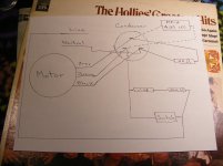
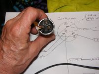
It appears there should be a single (two connection, film) motor run capacitor of value 3.7uF/150WVAC as shown in the final photo.
At some point, the extra capacitor may have been added in an attempt to make the motor run more smoothly. I would see how the motor runs with and without the piggyback capacitor. Film capacitors should not need replacing.
At some point, the extra capacitor may have been added in an attempt to make the motor run more smoothly. I would see how the motor runs with and without the piggyback capacitor. Film capacitors should not need replacing.
P.S. A three connection capacitor, with all three connections in circuit, would suggest a combined start/run capacitor. Follow ralph's suggestion of removing the clamp in order to verify, the start capacitance would be larger than the run capacitance.
Question: Is the capacitance 37uF in the final photo or 3.7uF?
Question: Is the capacitance 37uF in the final photo or 3.7uF?
That was my initial thought. I am getting a capacitance meter tomorrow. I will check things out. I hope to validate the dead capacitor. One thing I can't figure out is that the only specs on the can cap is 3.7uF. Could motor start and motor run caps both have this same value? Thank you.
I would hazard a guess that the piggyback capacitor is a 4μF, 150V (the K being a tolerance code).I am getting a capacitance meter tomorrow. I will check things out.
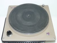
While we await verification, I've included a photo of the idler drive TT for all to see!
")
Attachments
So I got the capacitance meter and this is what I got. I arbitrarily assigned numbers to the three original capacitor terminals. 2&3-157pF, 1&3-168pF, 1&2-89pF. The capacitor that was piggybacked to the original, the one marked 4 (K) 150, measures 8.4uF. The capacitor wired on the terminal strip measures 332nF. I can see a 1 uF marked on this one but I am not sure if it is 1uF or .1uF. Thanks again.
Jim
Jim
420nF is 0.42uF which would be a reasonable reading for a 1uF cap.
It would appear that the large can capacitor is dead (since the capacitance readings are effectively zero).
To help understand why there are three terminals, please post a head-on photo of the business end and relate the terminals on the photo to those on the circuit diagram you supplied earlier.
It would appear that the large can capacitor is dead (since the capacitance readings are effectively zero).
To help understand why there are three terminals, please post a head-on photo of the business end and relate the terminals on the photo to those on the circuit diagram you supplied earlier.
- Home
- Source & Line
- Analogue Source
- Need Help With CEC FR-808 Turntable Wiring