The relative hotness is important. Did the resistor smoke when used with the original cap?I ran the motor with the new cap. The 2K ohm resistor instantly gets hot and after 5-10 seconds it actually starts to smoke!
A larger value of capacitance may be required.
It would be interesting to see the effect of putting the original capacitor in parallel with the new one!
It would be interesting to see the effect of putting the original capacitor in parallel with the new one!
With the original cap I could smell the heat right away and then a wisp of smoke. I can try the parallel caps if it won't hurt anything?
You didn't report the resistor was smoking when you ran the motor for a full 30 minutes using the 8uF cap - can you see why I am confused?Well, after running for about 1/2 hour it seems that the motor is running very hot. The capacitor that had been piggy-backed on measures approx. 8uF instead of the original 3.7uF. Could this be the problem?
You can try the parallel caps at your own risk, but connect only long enough to note the result - a matter of seconds rather than minutes.
If the motor is designed to run from a 100V supply at 0.1A, and we ignore pf correction we're looking at a dissipation of around 10W.
At the moment we're running from a 120V supply at 0.25A, a dissipation of 30W, so no surprise the motor runs too hot!
First you need to reduce the supply voltage! ideally run it via a step-down transformer, or via a Variac. As a 'get you going' solution try running it in series with a lamp, maybe 100W as a starting point. Check the voltage across the motor, if it's much less than 100V use a higher wattage bulb, if it's above 100V try a 75W or 60W bulb.
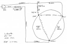
From further reading some of my old textbooks 🙂 it appears that the lower resistance winding should go directly across the supply, and the higher goes via the capacitor.
On that basis black - gray is the run winding, and black - brown is the 'start' winding that connects via the capacitor.
Hope this provides further food for thought, and just as an extra point please don't run the motor for more than a few seconds without checking the current draw is somewhere around the 0.1A mark otherwise there is a risk of burning out a winding.
Good Luck
At the moment we're running from a 120V supply at 0.25A, a dissipation of 30W, so no surprise the motor runs too hot!
First you need to reduce the supply voltage! ideally run it via a step-down transformer, or via a Variac. As a 'get you going' solution try running it in series with a lamp, maybe 100W as a starting point. Check the voltage across the motor, if it's much less than 100V use a higher wattage bulb, if it's above 100V try a 75W or 60W bulb.
From further reading some of my old textbooks 🙂 it appears that the lower resistance winding should go directly across the supply, and the higher goes via the capacitor.
On that basis black - gray is the run winding, and black - brown is the 'start' winding that connects via the capacitor.
Hope this provides further food for thought, and just as an extra point please don't run the motor for more than a few seconds without checking the current draw is somewhere around the 0.1A mark otherwise there is a risk of burning out a winding.
Good Luck
Thanks! That is certainly the way the Lafayette motor is wired (see post #6 and the attachment) so that's a good shout!From further reading some of my old textbooks 🙂 it appears that the lower resistance winding should go directly across the supply, and the higher goes via the capacitor. On that basis black - gray is the run winding, and black - brown is the 'start' winding that connects via the capacitor.
Rather than consider the resistance of the run winding, it makes more sense to consider its inductance as quoted below.
Permanent Split Capacitor Motor | HVAC Troubleshooting"The run winding is placed lower in the core material (than the start winding), which helps increase the inductance."
Knowing that the motor is designed to run off 100V and not 120V is a key factor in this refurbishment, well done for spotting that! Employing a method of voltage conversion is mandatory in order to use this turntable.
Attachments
This could be a cheap solution to the voltage conversion problem:
https://www.ebay.com/p/Kashimura-Ti...100v-120w-Max-D35/2283119888?iid=223488964045
https://www.ebay.com/p/Kashimura-Ti...100v-120w-Max-D35/2283119888?iid=223488964045
"For Japanese Electronics in US / 120V Countries."
Done a bit more investigating and it looks as though the 4uF capacitor my be too large.
It looks as though 2uF is closer to the mark, it's a pity this info isn't provided on the motor, but good approximation can be made by multiplying the full load current by 2560, then dividing the result by the supply voltage, giving us a value of 2.5uF.
It looks as though 2uF is closer to the mark, it's a pity this info isn't provided on the motor, but good approximation can be made by multiplying the full load current by 2560, then dividing the result by the supply voltage, giving us a value of 2.5uF.
I have found out that the paint mark is, indeed, significant!I have included two pics of the cap. Is what appears to be a white paint mark near the right hand terminal of any significance? Thank you.
Identifying Motor Capacitor Terminals | HVAC Troubleshooting"It is desirable to connect the identified capacitor terminal to the line side instead of to the motor start winding."
@ ralphfcooke:
Re value of cap - before purchasing another run capacitor, breadhead could test your suggestion by putting the 8μF and 4μF capacitors in series (Cseries = 2.7μF). 🙂
Good point re putting the capacitors in series.
As far as the white mark is concerned I think it relates more to a safety issue to ensure the foil with the higher voltage is further from the grounded case. As this is a 400V cap on a 100V supply I wouldn't be too concerned.
As far as the white mark is concerned I think it relates more to a safety issue to ensure the foil with the higher voltage is further from the grounded case. As this is a 400V cap on a 100V supply I wouldn't be too concerned.
Here's confirmation from the HVAC Troubleshooting site. (Some internet sources actually say the opposite, but HVAC appears more knowledgeable.)
Testing The Stator Winding | HVAC Troubleshooting"The start winding . . . should have a higher resistance than the run winding. This difference of resistance may not be great, but the start winding should have a higher resistance than the run winding."
You're right, there's information in both directions, but I agree with HVAC.
The best way (once the OP has a 100V supply available), is to try either way, with both 2.7, 4, and 8uF caps, and see which configuration is closest to the motor specs on the plate, i.e a current draw of around 0.1A and the smoothest running.
The best way (once the OP has a 100V supply available), is to try either way, with both 2.7, 4, and 8uF caps, and see which configuration is closest to the motor specs on the plate, i.e a current draw of around 0.1A and the smoothest running.
Sorry for not responding. I just had a terribly busy evening and day but rest assurd that I GREATLY APPRECIATE THIS HELP!! I do in fact have a variac. I just need ti figure out how to wire this thing now.
Comes from intimidation by superior intellects on this forum. Least I can do is spell "to" correctly. I can handle that 🙂
I am hoping to receive some detailed pictures of the original wiring from someone today. Will post results when received.
Sorry this took so long but I was extremely busy with other projects that I knew I could complete. Anyway, I tried wiring the 9.2 uf and the 4.2 uf caps in parallel and the current draw shot up to .39 amp. Not good for a .1 amp spec. motor. I then wired the caps in series. Hooray!!!! The motor now draws .08 amps. The resistor still gets somewhat hot but nothing like it did before.
Best,
Jim
Best,
Jim
- Home
- Source & Line
- Analogue Source
- Need Help With CEC FR-808 Turntable Wiring