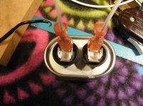
The green resistor appears to be an original fixture. If it was definitely wired in parallel with the start winding then I am unsure of its function.
On the occasions when a resistor is shown in relation to an induction motor, it is shown in series with the run capacitor as per the diagram in post #6 and in the attachment below. However, the value of the resistors shown is in the order of 200Ω rather than 2kΩ.
Let's wait and see how the motor runs with the new run capacitor before playing around with the resistor.
Attachments
I ran the motor with the new cap. The 2K ohm resistor instantly gets hot and after 5-10 seconds it actually starts to smoke! I measure 171 VAC across this resistor. Amperage draw actually went down, .37 to .28 amp with the new cap.
I'm not surprised the resistor gets hot as it's dissipating nearly 15 watts!
Surprised you didn't notice this last time you ran the motor.
Try running with the resistor removed.
Surprised you didn't notice this last time you ran the motor.
Try running with the resistor removed.
Motor seems to have more torque without the resistor. With the resistor in the circuit I could stop the pulley by pinching with my fingers. Without the resistor I can't but the motor also has more vibration with the resistor out of circuit. Would wiring the resistor in series hurt anything? Thank you!
At least the motor hasn't been fried - yet! 😉
Won't hurt (I hope!) to try the resistor in series with the capacitor, but worth checking its present resistance first.
Break the connection between the brown wire and the capacitor and insert the resistor into the gap.
Keep a look out for the motor overheating and switch off immediately if it's detected.
Would still like to know the type of capacitor you have obtained in order to eliminate possible causes.
I will be away from the computer for a wee while, but look forward to your report.
OK. With resistor installed as you specified the motor would hardly turn at all so immediately shut down. I have included two pics of the cap. Is what appears to be a white paint mark near the right hand terminal of any significance? Thank you.
Attachments
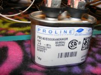
Capacitor is of required type and the paint mark is of no significance.
Check what the present resistance of the resistor is.
Check what the present resistance of the resistor is.
I'm flummoxed! Can't explain why the 2kΩ resistor only overheated when the new cap was introduced.
Does the green resistor actually have 2kΩ stamped on it?
We're shooting in the dark without a circuit diagram. Surprised that no one with experience of vintage turntable motor circuits has chipped in to set us on the path to enlightenment.
You say the motor ran, albeit with some vibration, when the 2kΩ resistor was removed. What is the current draw in that situation and is the motor overheating?
On the last photo of the original post there is a label plate. Could you take a photo of that and post it?, it might have some useful info.
Hi Ralph and thank you for helping. Picture is attached. I just ran the motor without the 2K ohm resistor for 25 minutes and I couldn't touch it for more than a second due to heat. I did notice on the plate it states 100V and I have about 119.7. Could this cause the heat?
Attachments
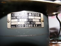
It won't help, Japan uses 100V and a 20% increase is significant. I'm more concerned about the difference in current draw.
Could you try connecting it with the higher resistance winding directly across the supply and the lower one via the capacitor?
Could you try connecting it with the higher resistance winding directly across the supply and the lower one via the capacitor?
Yes, try it in parallel with the winding, but in series with the capacitor, if that makes sense.
Welcome back! Hope you can help - I'm floundering!Could you try connecting it with the higher resistance winding directly across the supply and the lower one via the capacitor?
If I have interpretated the wiring correctly, the higher resistance run winding (black/brown; 309Ω) is already connected directly across the supply.
The 2kΩ resistor was originally in parallel with the lower resistance start winding (black/grey; 175Ω) and the combination was in series with the run capacitor.
This is the original configuration which appeared to work until the new capacitor was inserted, when the 2kΩ resistor went red hot!
Don't know if the motor is spinning, but my head certainly is!

Don't let the motor get that hot as you're in danger of burning out the windings, after which any hope of restoration would be over!I just ran the motor without the 2K ohm resistor for 25 minutes and I couldn't touch it for more than a second due to heat.
OK. I won't make the mistake of letting the motor get that hot again! I should clarify that the resistor did get hot with the original cap in. I am not sure whether it was as hot as with the new cap but I think it probably was.
- Home
- Source & Line
- Analogue Source
- Need Help With CEC FR-808 Turntable Wiring