Now I wonder if I can use the second circuit (MM with 44dB @1khz) and place your Head amp on front of it to use it also for MC
As a matter of fact I also designed a MC prepre that I built in a breadbord http://www.diyaudio.com/forums/analogue-source/323937-sziklai-jfet-input-mc-pre-pre.html#post5469472
You are right, I didn't understand what you asked.I see you misunderstood my question... what I wondered about was the possibility to place an opamp on the paradise IPS so to null the current flowing in the cart.
I was not asking how to mod the IPS of the paradise.
As a matter of fact , the meaning of IPS is still a mystery to me.
But since the paradise is openloop, you can separately put a servo on the input and the output.
See the example below.
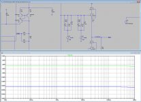
DC input voltage is 3uV and DC output voltage is 16uV.
And that even with transistor Q7 being of a different type, whatever the reason may be.
Hans
Attachments
Ricardo,
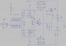
Here is a much better solution.
Current through the input pair remains the same for both sides as in the original design, and only a current is injected at the input to compensate for the Hfe differences of the various resistors.
Input offset voltage is now below 6 uV.
To control the output offset voltage, the originally existing mechanism has been used.
So in effect the three resistors at the input have been replaced by a simple servo, doing a much better job, that's all.
Hans
Attachments

You are right, I didn't understand what you asked.
As a matter of fact , the meaning of IPS is still a mystery to me.
In Put Stage. You could always null the input current after warm up once and hope that it does not drift much over time.
Thank you... that was what I was asking about relative to the original Paradise.
I left Q7 different because I wanted to see if I could mimic an input current due to different hfe between transistors. It must be a bc327-40 for the final sch.
And yes IPS (Input stage)
Now I will not bother you more with the paradise. I was present from the start, I was the beta tester and I also designed one of the RIAA filters, but now it is finished and we should not mod it.
Now back to the incarnation.... do you believe I could use your head amp before the jfet MM version so I can have a phono compatible with MM and MC ?
First of all, your so called "reincarnation" does a wonderfull job for MC with exceptional low input noise.Now back to the incarnation.... do you believe I could use your head amp before the jfet MM version so I can have a phono compatible with MM and MC ?
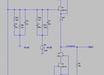
Since overall gain is only determined by four components in the Riaa network, I would opt for using two Riaa networks, one giving 60dB and the other giving 40dB overall gain, by switching between one of both to Gnd,
This will give you by far the easiest and most elegant way to have both options available.
Using an extra head amp as proposed in this thread will be theoretically possible, but this design is differential in/ differential out, so you will also have to add a differential to SE converter, making things a lot more complicated as the solution proposed above with your "reincarnation".
Hans
Here it is.Thank you so much Hans
I will scale the RIAA filter and see where that leads me.
Best
Ricardo
Green 61dB for MC, Blue 41 dB gain for MM.
Hans
Attachments
Thank you so much Hans... now I must add a circuit that enables switching without causing noises in the output.
The solution is not that complex, see below.Thank you so much Hans... now I must add a circuit that enables switching without causing noises in the output.
The 60 dB network can stay connected to earth all time.
The second network, resulting in 40dB, should be switched in parallel when using MM.
I don't think that much drama will happen when switching.
Hans
Attachments
Waking the thread up as helping someone out who is trying to rip vinyl with a 2i2 direct and not suprisingly having little luck. Now I was going to recommend the resistive load approach except for the fact that he is using an RB300 tonearm which grounds the arm to left channel - so forcing single ended use. And here is where I always get confused. Does grounding one input give an additional noise penalty? I don't think so...
(other option is to ignore the screening issues and just connect as balanced even though it isn't as a test)
(other option is to ignore the screening issues and just connect as balanced even though it isn't as a test)
Bill,
In what way had this someone little luck connecting his MM element to the 2i2 ?
In any case the TT chassis should be connected via the cable shield to the 2i2 pin 1, and in case of SE also to pin 3 and lead the hot signal from the MM to pin 2.
This SE connection will not directly lead to extra noise, but CMRR will go out of the window.
But never be tempted not to connect to pin 1, unless you use a separate wire going from the TT chassis to the 2i2 chassis.
What exactly did you mean with the resistive load approach, a way to be able to skip the 75usec pole ?
Hans
He was using the instrument input (guitar) which I believe is high impedance (spec not clear on this) and was getting a large HF peak in the response (as expected with incorrect loading on an audio technica cartridge).
So figured it was worth trying your idea to do the 75us pole with a resistor. His first attempt without an additional resistor seems to have caused an instability which is worrying.
So figured it was worth trying your idea to do the 75us pole with a resistor. His first attempt without an additional resistor seems to have caused an instability which is worrying.
The instrument input has an 1Meg impedance, so he should have loaded the cart additionally with 47K.He was using the instrument input (guitar) which I believe is high impedance (spec not clear on this) and was getting a large HF peak in the response (as expected with incorrect loading on an audio technica cartridge).
So figured it was worth trying your idea to do the 75us pole with a resistor. His first attempt without an additional resistor seems to have caused an instability which is worrying.
The Mic input is 3K and depending on the Cart also needs some additional loading to get the pole exactly at 75use. However, when the instrument input does not work with 47K, I see no reason why a different loading with a digital filter without the 75usec should work.
Hans
Ah. that was the missing information. I couldn't find the instrument input impedance. Thank you.
Well after a year of pontificating I got a good deal on a focusrite 6i6 which came today. There is a fighting chance I can start trying things out 🙂
Hi Bill,Well after a year of pontificating I got a good deal on a focusrite 6i6 which came today. There is a fighting chance I can start trying things out 🙂
Still all the best for 2019.
I was curious to hear the progress on your Aurak efforts.
When I can help you with your 6i6, just let me know.
Hans
- Home
- Source & Line
- Analogue Source
- Designing a universal diff-in/diff-out Head Amp