When going SE, you could place a Fet buffer on the cart without the need for extra wires in the Arm, but you will still need a few passive components at the other side of the Arm to connect to the supply.
Hans
Hans
Yes it was the big caps that made me realise that phantom powered mini boards were, whilst possible NOT DIY. I do want to try your phantom MC headamp sometime as well.
What's inside the Clearaudio Active Headshell? I suppose it does not need to be phantom power. This is not the only one I have seen over the years.
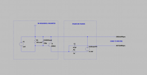
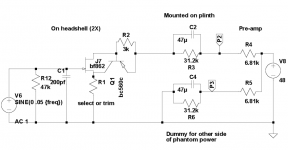
Also the phantom power schematic in the other guys open hardware section does not make sense, 39K series resistance leaves precious little current from the 48V.
EDIT - Just thought of something, a hearing aid battery could provide some negative bias to a JFET circuit and eliminate some caps. I don't think there needs to be any non-SMT caps in the right circuit.
Last edited:
No idea, but it uses a 9 pin din on its cable so likely NOT phantom powered. And only available to clearaudio tonearm purchasers.
Right, I found the numbers that add up but it's 80uA per channel from the phantom supply. At 2K input for say a Scarlett 2i2 that's only 80mV rail to rail??? Their own application shows a 68K termination with indeterminate cable capacitance shunting it (even mentioning that 200pF there is bad).
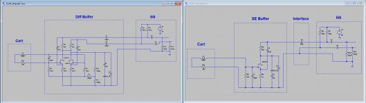
Here some ideas:
1) An SE version where a PCB could be mounted on the Cart with an interface board somewhere in the TT cabinet, or alternatively both on one PCB in the TT cabinet.
2) A dif version based on Scotts design, to be mounted in the TT cabinet.
Both versions have been tested in LTSpice. The SE version had -60dB THD 50mV@20Khz.
But when placing a PCB in the Cabinet, why not going for the Diff version, it still is very simple to realize.
Hans
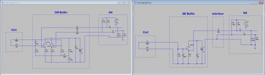
Attachments
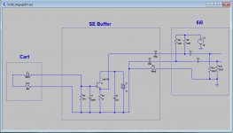
Wth a 9V battery, things can be made a bit simpler.
But no longer for Cart mounting in this case.
Like this
But no longer for Cart mounting in this case.
Like this
Attachments
Last edited:
The first one in #127 is not drawing any power (need to remove two caps). I would bypass R11 so it can't add common mode noise even though this should not be a problem. The 2SK170 won't draw enough current with 1K in source and gate grounded.
Last edited:
And this SE version with Battery is even behaving like a differential version.
Hans
hi Hans!
if you make a jfet buffer like this you can fit it on cart connections
ups, you cannot load the cart with R1 probably...
Attachments
Last edited:
hi Hans!
if you make a jfet buffer like this you can fit it on cart connections
ups, you cannot load the cart with R1 probably...
As drawn the gate is forward biased.
As drawn the gate is forward biased.
that was my ups😉
you can always use the version with the gain, source res is optional
Attachments

Ha, ha, what a silly mix up with other versions that were tested.The first one in #127 is not drawing any power (need to remove two caps). I would bypass R11 so it can't add common mode noise even though this should not be a problem. The 2SK170 won't draw enough current with 1K in source and gate grounded.
Of course these caps do not belong there.
The 2KS170 draws 500uA in my model, more than enough to get the -60dB distortion figure that I measured at 50mV@20Khz.
IDSS of this Fet in my model is 10mA.
Hans

that was my ups😉
you can always use the version with the gain, source res is optional
You need the source resistor for a practical circuit or many BF862's will saturate. Also you would want to have modest gain on MM with some matching too. I will do a little design work with the FET's Bill found, this could be the smallest choice of all. I have an idea that would at most require removing the ground clip if the cartridge has one. This should not be a noise problem since the circuit would insert only 100 Ohms or so there.
The 2KS170 draws 500uA in my model, more than enough to get the -60dB distortion figure that I measured at 50mV@20Khz.
IDSS of this Fet in my model is 10mA.
Just me, I'm always thinking of using any FET in the entire Idss range.
Hi Padamiecki,that was my ups😉
you can always use the version with the gain, source res is optional
I have a bit of a problem with your diagram because:
1) The full IDSS wants to flow, some 10-15mA in this case which is a waste.
2) The drain resistor has to be reduced to get the drain voltage well above a few volts, in this case like 500 Ohm for a 9V battery.
3) It does not function as a buffer but as an amplifier with unknown gain, at least more than 20dB.
Hans
- Home
- Source & Line
- Analogue Source
- Designing a universal diff-in/diff-out Head Amp