I'm particularly interested in the current input version, but that is just because my current MC preamp is based on a differential AD797 voltage input.Both look exceedingly transparent. Which would you chose?
Hans
🙂 Me too.
Reading the 2i2 spec again I not that the green LED comes on at -23dBFS, so if I have not missed something you could use that to set gain for a cartridge using a 0dB mono test tone so if the green light just comes on you are good to go.
Reading the 2i2 spec again I not that the green LED comes on at -23dBFS, so if I have not missed something you could use that to set gain for a cartridge using a 0dB mono test tone so if the green light just comes on you are good to go.
This is the current input version.
Hans, would not this input circuit do the same job? The impedances are balanced (R1=R2) and you could get rid off the NUL-knot...
Attachments
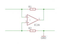
No, I referred just to left part of your circuit. The couling-caps have still have to be inserted... This is basically an I/V-converter and R2 ensures balanced operation
Thank you for your contribution. Maybe you can draw a more complete circuit, because I don’t get the message.
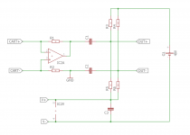
This is what I meant, but now I'm a bit confused myself... 🙂 Never used phantom power...
Attachments
Last edited:
This circuit doesn’t work for several reasons.
1) the Cart has no reference voltage, the Nul in my case, so everything will collapse to Gnd.
2) when you give the Cart a voltage somewhere in between gnd and opamp supply, a DC current will flow through the Cart, that’s exactly what we don’t want.
3) when Cart is playing, opamp tries to Produce a voltage around zero volt, which is not possible with V- at Gnd.
So to let this work, The Cart should get a reference voltage somewhere in between and R2 should be connected to this same voltage. And there you are, that’s what I have done.
Hans
Scott, one could even consider to leave the MM impedance convertor and to plug the MM Cart straight into the 2i2's 3KOhm Mic input, without even using Phantom Power in that case.
You will need a different Riaa correction network just like the Aurak design.
With a simple formula like (X*Lcart - Rcart), the missing link in the form of just one resistor can be added to match the digital Riaa filter.
Hans
You will need a different Riaa correction network just like the Aurak design.
With a simple formula like (X*Lcart - Rcart), the missing link in the form of just one resistor can be added to match the digital Riaa filter.
Hans
I did wonder that when I first saw the 3k spec, but you are into the realms of having a noise penalty from it (remember the discussion on cooled cartridge loading). It's certainly worth considering or even testing.
I did wonder that when I first saw the 3k spec, but you are into the realms of having a noise penalty from it (remember the discussion on cooled cartridge loading). It's certainly worth considering or even testing.
I don’t think you have to worry at all, eq input noise is only 3.2 nV/ rtHz.
Hans
Measuring phono stage RIAA accuracy with a computer
You show a 7.7dB noise penalty from a 6k load. 3k will not only put the HF roll off way too low but also be even noisier? Of course as usual I will have missed something 🙂
You show a 7.7dB noise penalty from a 6k load. 3k will not only put the HF roll off way too low but also be even noisier? Of course as usual I will have missed something 🙂
You will need a different Riaa correction network just like the Aurak design.
With a simple formula like (X*Lcart - Rcart), the missing link in the form of just one resistor can be added to match the digital Riaa filter.
You could but every cart and sound card would need a different set of numbers and the noise hit might be audible.
Last edited:
With just one resistor all differences between sound cards and Carts can be solved.You could but every cart and sound card would need a different set of numbers and the noise hit might be audible.
But, it wouldn't be me if I had not simulated the effect on noise, and the effect was a S/N of 72.7 dBA, when using the 2i2 figures for two different cartridges.
What I used was a pole at 71.4usec.
For a 500mH cart with a Rcart of 600Ohm, this meant adding one series resistor of 400 Ohm
For a 580mH Cart with Rcart od 460 Ohm, a series resistor of 1660 Ohm had to be added.
The Math behind, 1) (600+400+6k)/0.5 = (460+1660+6k)/0.58.
For another sound card the 6K (=2x3k) might have another value and can be adjusted with the extra series resistor.
The question is though, is 72.7 dBa good enough or not.
Hans
When putting the pole at 75usec, the third Riaa time constant might be completely left without further correction.
The added resistance for a 580mH/460Ohm Cart becomes in that case 1273 Ohm, and for the 500mH/600Ohm cartbecomes 67 Ohm.
It might become a bit narrow for some cartridges and it has no advantage on noise performance.
Anyhow, the calculated 72.7 dBA is with the Cart connected, where most suppliers specify with input short circuited.
And be aware, noise is still quite a bit above the LP's surface noise.
To conclude: it costs no penny to try, and you can't damage anything.
Hans
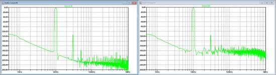
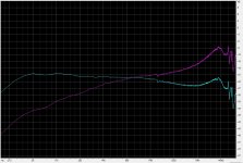
OK, I ran this last night and I hope it confuses others as it did me at first. Pink noise from one of the STR series LP's, I only have one TRS to XLR adaptor so I could only do one channel of the 2i2 direct differential in and the same channel through my pre-amp which measures with a synthesized RIAA pre-emphasis +-0.1dB. This is a Grado MI cartridge.
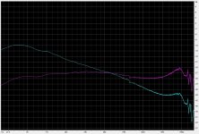
Plot 1 - Pink is direct in and blue is the RIAA pre-amp. Please bear with my reasoning. What I see here is with direct in we have the pre-emphasis acting like a negative "pinking" (RIAA endpoints are -20dB and +20dB over 4 decades). What's left are the two bumps when you straighten out the RIAA. The blue plot should be straight (the 14K peaking has been in every Grado I have ever tried) and 1/f (pink). All the plots are normalized to be equal at 1kHz.
Plot 2- I used an un-pinking FFT filter on the previous plot. I am disturbed by the slight residual tilt on the RIAA pre-amp, so I need to check a more modern pink noise test record, but it basically makes sense.
The noise floor with reference to a blank groove was within 1 dB on both plots.
Attachments
- Home
- Source & Line
- Analogue Source
- Designing a universal diff-in/diff-out Head Amp