George,
I made the Sim with your LF356+300k setup with resp. 1k, 10k and 100k, see images below for the modulus and the Re value.
LF356 Spice model was downloaded from TI.
It is quite a difference from what you measure.
So if it can't be the LF356 or the EMU, could it possibly be REW that you are using ?
Hans
Attachments

@Hans: Didn't George say that he got the same result using two completely different measurments methods or did I misunderstand that?
Mogens
Mogens
Hi Mogens, this is correct.
Post#1195 Cartridge dynamic behaviour has no E-MU and no REW involved.
The only commonalities with post #1413 Cartridge dynamic behaviour is they use the same LF356 dead bug I/V circuit and there is Excel involved.
Calibration resistance measurement errors with both setups follow the same pattern but with E-MU and REW are quite smaller.
Post #524 Cartridge dynamic behaviour is not impedance measurement but through loss, nevertheless it shows self resonance frequency (no LF356 I/V, no E-MU, no REW, no Excel)
Hans, I suggest to leave it as is and revisit it when you will have the cartridges on your bench. 🙂
George
O.k. We’ll leave your test gear for the time being, no problem.Hi Mogens, this is correct.
Post#1195 Cartridge dynamic behaviour has no E-MU and no REW involved.
The only commonalities with post #1413 Cartridge dynamic behaviour is they use the same LF356 dead bug I/V circuit and there is Excel involved.
Calibration resistance measurement errors with both setups follow the same pattern but with E-MU and REW are quite smaller.
Post #524 Cartridge dynamic behaviour is not impedance measurement but through loss, nevertheless it shows self resonance frequency (no LF356 I/V, no E-MU, no REW, no Excel)
Hans, I suggest to leave it as is and revisit it when you will have the cartridges on your bench. 🙂
George
I will test my set with the same 3 resistors and see how it compares to a sim.
Hans
Not that I have any problem if I am proven wrong, on the contrary.O.k. We’ll leave your test gear for the time being, no problem.
Only to save resources, I want to finish the distortion test and send the carts for verification to you.
George
George, good newsNot that I have any problem if I am proven wrong, on the contrary.
Only to save resources, I want to finish the distortion test and send the carts for verification to you.
George
It was a very useful exercise to test my gear telling that you are the one who was right with Fres.
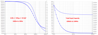
A test with a 1k, 10k and a 100k resistor showed that the input capacity of my test setup is not at all just the scopes specified 13pF +/- 1pF that I used, but a much higher 23.5pF.
I can't believe that the scopes specs are wrong so the combination of BNC/Cinch + Cinch connector must have an unbelievable high capacity of 10.5pF !!
Corrected for this 23.5pF value, FR is perfectly straight within 1% up to 10MHz with all three resistor values.
See images below, at the left 110K par to 1Meg//23.5pF and the second image with the same combination up to 10MHz to show the total capacity of 23.5pF.
That means that I will have to redo all work, sniff, now with the corrected 10.5pF lesser value for the par. cap in the Cart.
And to give you a first impression, yes the OM10 now lands at a Fres of ca. 75kHz.
Fortunately I still have all original measurements, but it will be hard working to correct all the 8 Carts, pffff.....
The good news is that my measurement gear proves to be very accurate and reliable when taking the 23.5pF input cap into account.
Hans
Attachments
Last edited:
I can't believe that the scopes specs are wrong so the combination of BNC/Cinch + Cinch connector must have an unbelievable high capacity of 10.5pF !!
If they are designed for 50 Ohm systems 10cm should give about 10pF, that's not that long.
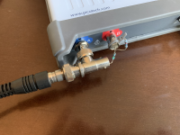
It is much shorter with 1.5cm.If they are designed for 50 Ohm systems 10cm should give about 10pF, that's not that long.
The Cinch plug inserted in it and without any wiring directly soldered to the DUT.
Hans
Attachments

The good news is that my measurement gear proves to be very accurate and reliable when taking the 23.5pF input cap into account.

Fine Hans. That’s the important part.
Now, take your time -no one is in a hurry for all this retro stuff- and cautiously redo all the equivalent circuits.
I suggest to post all the new equivalent circuits in one post, so we will all know where to find the correct ones.
I may repeat myself here, I think detailed cartridge equivalent circuits are important tools for those who design, modify or trim phono cartridge preamplifiers.
George
I suggest to post all the new equivalent circuits in one post, so we will all know where to find the correct ones.
George
Of course, all in one.
I measured the input capacity of my scope using the shortest possible connection, see image below, and indeed removing this BNC to Cinch adapter reduced the input capacity by an unbelievable 10pF !!
So be aware when using such an adapter.
Hans
Attachments
George and Hans: Two thumbs way up for your collaboration on this. I think we really have a new piece of the puzzle here. Looking forward to now making time to do the next meaurements
My feeling (and without having access to the Van Maanen papers on this) is that we've hit on a more accurate generator model than before which (to me) is the cornerstone for trying to discover more on how the annoying moving bit interacts 🙂
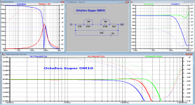
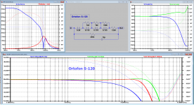
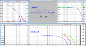
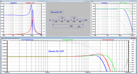
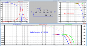
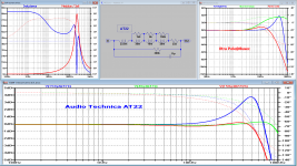
O.k, here is the lot, 8 completely different Carts, now corrected for the 10pF BNC to Cinch adapter, thanks to George, showing how important it is to have more than one person to check things.
The three images for each Cart are showing on top resp. the transfer curve, the replacement circuit and the FR with a usual 47k//150pF voltage amp termination and in the same image the FR with a virt. gnd amp like the Aurak.
In case the latter is too violent in the HF, I have shown what an extra pole could do.
The fourth image below the three shows what effect a different termination from 47k/150pF can sort.
Hans
Attachments
-
 Ortofon Super OM10-2.png152 KB · Views: 224
 -
 Ortofon S-120-2.png147.8 KB · Views: 223
 -
 Ortofon 40-2.png90.4 KB · Views: 332
 -
 Deno DL-109-2.png158 KB · Views: 324
 -
 Deno DL-107-2.png151.9 KB · Views: 338
 -
 AT150MLX-2.png141.3 KB · Views: 422
 -
 AT22-2.png266.7 KB · Views: 326
 -
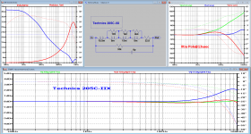 Technics 205C-IIX-2.png87.5 KB · Views: 236
Last edited:
Once again, Thanks Hans.
Great job!
And a great Thanks to Bill for supplying all these cartridges.
George
Great job!
And a great Thanks to Bill for supplying all these cartridges.
George
+1 to Hans
@George: Good to have them out the box and being useful! I'm still digesting the results. I am interested that the superOM seems the best match for current loading with the 1960s DL-107 being a close second but harder to setup for.
The biggest suprise is how loading can get good behavior out the hoofing great coil on the S-120. This may yet prove to be a useful cartridge.
A minor back to the drawing board as to how to implement some of this in a domestically acceptable format but I have some ideas.
Of course we are trying to polish the unpolishable here and TBH none of the plots are that shabby even unoptimised. I suspect there is more value looking at the phase than level in deciding which is optimal loading?
My personal view after this whole exercise is:Of course we are trying to polish the unpolishable here and TBH none of the plots are that shabby even unoptimised. I suspect there is more value looking at the phase than level in deciding which is optimal loading?
1) more than ever is it importants to know how much the motor voltage deviates from the flat-spectrum voltage source that I used and
2) since loading seems to have large influence on the Carts FR, a voltage preamp built into the plinth with sufficient choice of switchable caps and resistors could be an answer to get the best out of every Cart.
3) a virtual gnd amp, nicely eliminating the influence of the cable capacitance, seems not being the right answer for all Carts.
Hans
- Status
- Not open for further replies.
- Home
- Source & Line
- Analogue Source
- Cartridge dynamic behaviour