Hi all
Tarnished contacts cleaning is the first thing I did.
I haven’t tried putting the HD in the freezer. I read somewhere that this may damage the heads if some ice forms inside.
Today I bought a used HD (for 25Euros) same P/N as mine, same firmware.
I tested it and it was OK.
Then I took out the logic board and installed it on mine. The disk remained unlisted under Windows. The bootup menu was listing this HD as failed.
The irony is that the Seagate diagnostic tools for Windows list the HD and all tests show it as healthy.
Then I installed on this logicboard the ROM IC that I removed from mine.
Now the HD is temporary listed under Windows but any action on it is denied due to I/O error as the message says. (the same message that was initially displayed before I started doing anything. The spinning sound is still click free.
I don’t think I can do something more with this (except for the freezer trick as the last one).
>obituary end.
Yesterday I found an old dump of my technical data from this HD (a mere 56GB from Dec 2014).
Time to start collecting new data.🙂
George
This means a farewell to many years of blood, sweat and tears.Hi all
I don’t think I can do something more with this (except for the freezer trick as the last one).
>obituary end.
Yesterday I found an old dump of my technical data from this HD (a mere 56GB from Dec 2014).
Time to start collecting new data.🙂
George
I feel sorry for you.
Hans
HDDs have inbuilt diagnostics called SMART, and if the interface is working it's perhaps worth putting the drive back to its original configuration and reading the smart data via freeware SW which runs on the PC?I don’t think I can do something more with this (except for the freezer trick as the last one).
>obituary end.
In some drives, part of the firmware is written to the disc, and it has to boot. Also PCBs can't necessarily be swapped between drives of the same type, serial number checks, servo params and defect maps are hard written to the platters factory build time.
Whilst there's even a small chance, I'd still encouraget trying to read SMART data to see what's going on, you never know it still might be file system corruption? And, if you can boot to DOS on the internal drive, and the external drive hardware will mount for DOS, run chkdsk on the external drive to report/fix file system errors? It's all still DOS under the shiny clothes.
LD
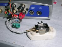
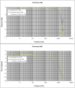
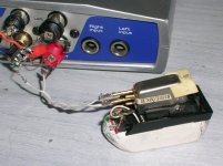
Back to the subject of the thread.
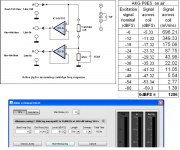
Measurements done with REW sw.
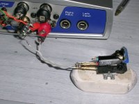
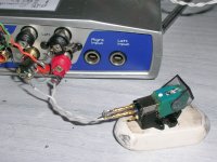
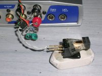
One set of measurements with the cartridge as shown on schematic.
Another set of measurements with a short in place of the cartridge coil.
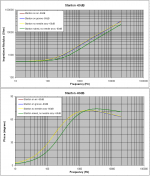
Both measurement sets exported as txt files and imported into MS Excel. No smoothing applied.
At the diagrams you see the result of [cartridge set] – [short set].
This subtraction removes any jig’s freq response and phase influence from the result.
George
Measurements done with REW sw.
One set of measurements with the cartridge as shown on schematic.
Another set of measurements with a short in place of the cartridge coil.
Both measurement sets exported as txt files and imported into MS Excel. No smoothing applied.
At the diagrams you see the result of [cartridge set] – [short set].
This subtraction removes any jig’s freq response and phase influence from the result.
George
Attachments

Windows ME was the last version which was based on DOS. Since then the base has been Windows NT, which was a complete rewrite allegedly based somewhat on VAX/VMS concepts.luckythedog said:It's all still DOS under the shiny clothes.
YouTubeI have tried any remedy trick I found on youtube.
Next action is hammer it, then pour some alcohol over the remains, throw a match and watch the scene
George,Back to the subject of the thread.
Measurements done with REW sw.
One set of measurements with the cartridge as shown on schematic.
Another set of measurements with a short in place of the cartridge coil.
Both measurement sets exported as txt files and imported into MS Excel. No smoothing applied.
At the diagrams you see the result of [cartridge set] – [short set].
This subtraction removes any jig’s freq response and phase influence from the result.
George
Great set of measurements.
What are your conclusions and how should this information be used in relation to dynamic cartridge behaviour.
Hans
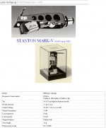
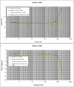
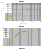
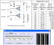
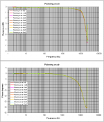
Next, Stanton MK V Impedance measurement.
Again, measurements done with REW sw. Measurement sets exported as txt files and imported into MS Excel. 1/6 oct smoothing applied.
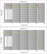
First three attachments is result of measurement jig’s characterization with calibration resistors. Not very bad for using a single reference resistor across so wide an impedance range.
George
Again, measurements done with REW sw. Measurement sets exported as txt files and imported into MS Excel. 1/6 oct smoothing applied.
First three attachments is result of measurement jig’s characterization with calibration resistors. Not very bad for using a single reference resistor across so wide an impedance range.
George
Attachments
-
 5 Stanton -60dB impedance.PNG64.3 KB · Views: 111
 -
 4 Stanton -6dB impedance.PNG65.6 KB · Views: 111
 -
 3 Stanton on air impedance at all signal level.PNG62.9 KB · Views: 123
 -
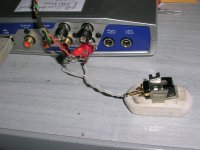
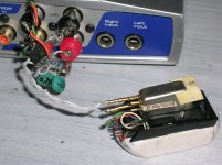
 2 measuring jig.PNG68.3 KB · Views: 103
 -
 1 photo.JPG924.7 KB · Views: 118
 -
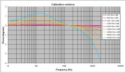 03 Calibration resistors phase.PNG35.1 KB · Views: 125
 -
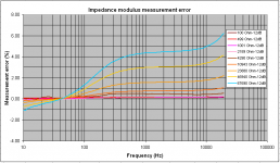 02 Impedance modulus measurement error.PNG35.4 KB · Views: 118
 -
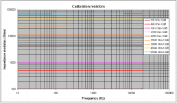 01 Calibration resistors impedance modulus.PNG29.2 KB · Views: 125
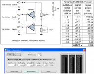
George,
Great set of measurements.
What are your conclusions and how should this information be used in relation to dynamic cartridge behaviour.
Thank you Hans
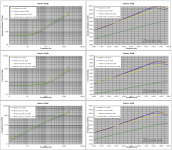
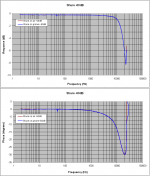
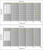
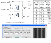
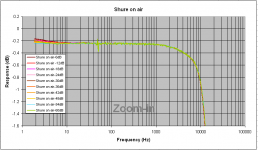
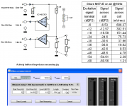
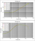
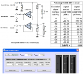
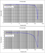
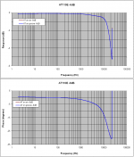
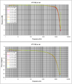
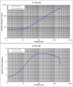
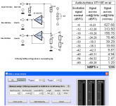
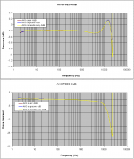
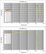
The excitation signal was from –14dB to +41dB ref 5mV, enough to cover the dynamics of a musical crescendo from p to fff
Within this signal range these measurements don’t show any change in behavior. Maybe there might be something at an even lower excitation level due to the core permeability nonlinearity at very low flux levels (initial permeability).
A secondary observation is that the moving parts of the motor don’t affect the measurements almost at all, another indication of very weak reciprocity.
Yet, the metal shielding of this cartridge affect the performance above 1kHz quite a lot.
George
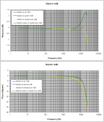
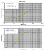
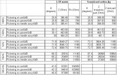
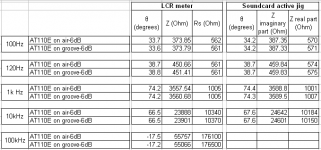
Continuation of post #189
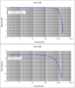
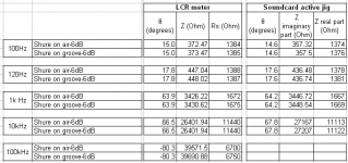
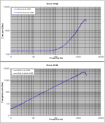
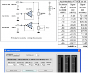
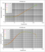
I extracted the real and imaginary parts of the Z modulus.
It is good that there is close match between the measurements obtained from the LCR meter and those from the soundcard+active jig
Note: The 100kHz data for the soundcard is nonvalid. It is only an estimation through visually extending the curves from 20kHz to 100kHz)
George
Attachments
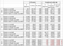

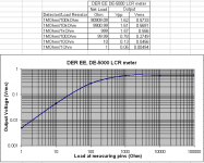
What is the measurement level, LCR meters tend to test at far higher levels than normal operation?
David I measured it. It’s a sinewave with amplitude varying depending on the DUT’s impedance.
George
Attachments
Shure M97xE response
George
George
Attachments
-
 5 Shure -60dB.PNG58.4 KB · Views: 129
 -
 4 Shure -6dB.PNG55.5 KB · Views: 120
 -
 3 Shure on air all signal levels.PNG60.3 KB · Views: 120
 -
 2 active jig and signal level.PNG62.9 KB · Views: 124
 -
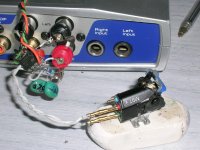 1 Photo.JPG916.1 KB · Views: 127
 -
 0 Shure specs.PNG86.5 KB · Views: 253
 -
 6 Shure on air all levels zoom-in.PNG33.9 KB · Views: 107
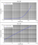
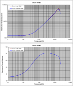
Shure M97xE impedance
George
George
Attachments
-
 8 comparison btn LCR meter and soundcard readings.PNG18.5 KB · Views: 110
 -
 7 Shure -60dB Z real and imaginary parts.PNG56.8 KB · Views: 98
 -
 6 Shure -6dB Z real and imaginary parts.PNG57.2 KB · Views: 99
 -
 5 Shure -60dB Impedance.PNG65.6 KB · Views: 95
 -
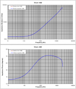 4 Shure -6dB impedance.PNG64.5 KB · Views: 115
 -
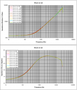 3 Shure on air Impedance at all signal levels.PNG63.7 KB · Views: 127
 -
 2 measuring jig.PNG62.3 KB · Views: 105
 -
 1 Photo.JPG926.5 KB · Views: 109
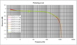
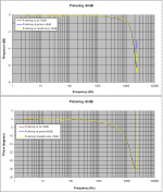
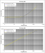
Pickering 950EE MK II response
George
George
Attachments
-
 6 Pickering on air all signal levels-zoom-in.PNG35.3 KB · Views: 96
 -
 5 Pickering -60dB.PNG58.5 KB · Views: 87
 -
 4 Pickering -6dB.PNG51.3 KB · Views: 91
 -
 3 Pickering on air all signal levels.PNG64.8 KB · Views: 102
 -
 2 active jig and signal level.PNG63.1 KB · Views: 97
 -
 1 Photo.jpg349.1 KB · Views: 91
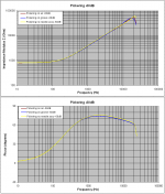
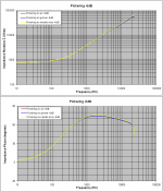
Pickering 950EE MK II impedance
George
George
Attachments
-
 8 comparison btn LCR meter and soundcard readings.PNG25.2 KB · Views: 94
 -
 7 Pickering on air -60dB real & imaginary Impedance.PNG56.1 KB · Views: 93
 -
 6 Pickering on air -6dB real & imaginary Impedance.PNG58.5 KB · Views: 83
 -
 5 Pickering on air Impedance-60dB.PNG64.4 KB · Views: 90
 -
 4 Pickering on air Impedance-6dB.PNG63.5 KB · Views: 92
 -
 3 Pickering on air Impedance all signal levels.PNG63.7 KB · Views: 97
 -
 2 measuring jig.PNG65.2 KB · Views: 94
 -
 1 photo.jpg353.4 KB · Views: 95
Audio-technica AT110E response
George
George
Attachments
-
 6 AT response on air all signal levels-zoom-in.PNG33.6 KB · Views: 102
 -
 5 AT response-60dB.PNG58.8 KB · Views: 97
 -
 4 AT response-6dB.PNG53.6 KB · Views: 101
 -
 3 AT response on air all signal levels.PNG61.8 KB · Views: 104
 -
 2 active jig and signal level.PNG65.2 KB · Views: 113
 -
 1 Photo.JPG914.9 KB · Views: 122
 -
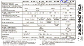 0 specs.PNG574.2 KB · Views: 87
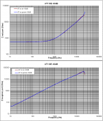
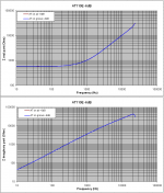
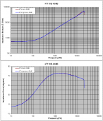
Audio-technica AT110E impedance
George
George
Attachments
-
 8 comparison btn LCR meter and soundcard readings.PNG18.1 KB · Views: 92
 -
 7 AT -60dB real & imaginary impedance parts.PNG61.1 KB · Views: 90
 -
 6 AT -6dB real & imaginary impedance parts.PNG55.9 KB · Views: 100
 -
 5 AT impedance -60dB.PNG64.5 KB · Views: 96
 -
 4 AT impedance -6dB.PNG63.4 KB · Views: 96
 -
 3 AT impedance on air at all signal levels.PNG63.1 KB · Views: 92
 -
 2 measuring jig.PNG66.7 KB · Views: 92
 -
 1 Photo.JPG912.9 KB · Views: 98
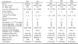
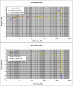
AKG P8ES response
George
George
Attachments
- Status
- Not open for further replies.
- Home
- Source & Line
- Analogue Source
- Cartridge dynamic behaviour