You can test the sensor output by holding a magnet over it and a voltmeter between ground and the sensor output. It should be high with no magnet, +4.5v or so, and with the magnet over it drops to about .5v. The other thing to check is the sensor is polarity sensitive to the magnet, try turning the magnet around and try again.
Good luck.
Good luck.
thanks the both of you. I have my pins correct. I think I've narrowed it down too my ability to smd solder. I'll try another this weekend
Would something like this work as an alternative
Hall Effect Magnetic Sensor Module, 3144E A3144 Hall Effect Sensor KY-003 DC 5V for Arduino PIC AVR Smart Cars by MUZHI(6 Pcs) https://a.co/d/6cXDM7M
Would something like this work as an alternative
Hall Effect Magnetic Sensor Module, 3144E A3144 Hall Effect Sensor KY-003 DC 5V for Arduino PIC AVR Smart Cars by MUZHI(6 Pcs) https://a.co/d/6cXDM7M
Last edited:
Yes i believe it shouldthanks the both of you. I have my pins correct. I think I've narrowed it down too my ability to smd solder. I'll try another this weekend
Would something like this work as an alternative
Hall Effect Magnetic Sensor Module, 3144E A3144 Hall Effect Sensor KY-003 DC 5V for Arduino PIC AVR Smart Cars by MUZHI(6 Pcs) https://a.co/d/6cXDM7M
Thanks $5 for 5, One day shipping with worth a try 🤷🏻. Probably not as low profile as pyramidsYes i believe it should
A couple months back I laid out a PCB for the Hall sensor, 12mm x 15mm, using the Diode Inc. AH3376-SA-7 at $0.63 each, the PCBs were $5 for 10 pieces. So a little over $1 per sensor board. Last night I got a chance to test it. I don't find that is works any better than the Littlefuse 55100-3H-02-A, but it is a tenth the cost.
Thanks for the really cool project to all of those involved! finally finished!!


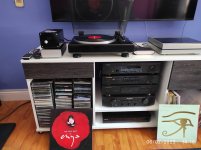
Getting back to my turntable project - SG4 and MA3D with the intended motor to replace the motor on my LENCO. Only thing left is the idler arm!
I have greatly improved where I was when I put this aside to work on my loudspeakers but there is still a slow drift in speed and I would like to try the ARDUINO to stabilize this. The width of the drift is less than 1 rpm.
I am using ROADRUNNER to monitor speed - what I am wondering is whether the ROADRUNNER sensor could drive both the ROADRUNNER and the ARDUINO or will I need to use two separate sensors?
Hoping the great PYRAMID is still looking here.
Thanks and take care.
AIWA AP2400 MODIFIED WITH DIGITAL TACHOMETER AND ARM LIFT WITH SERVO.
Hello. Looking around the forum, I found this thread.
I always wanted to make a turntable with a digital tachometer.
I show you a crazy thing that I did with an Aiwa turntable from the year 1980 direct transmission, which made the plinth with MDF, removed the power supply and speed control and placed it in a separate box. I added a digital tachometer with arduino, and also with arduino driving a servomotor and relay I made an arm lift at the end of the vinyl with engine shutdown.
I have tried to upload the tachometer and servo files. I haven't managed to do it.
Attachments
So the sensor output should drive 2 inputs. Give it a try to find out for sure. If don't then you can put a couple hex inverters between to drive the inputs.what I am wondering is whether the ROADRUNNER sensor could drive both the ROADRUNNER and the ARDUINO or will I need to use two separate sensors?
johnhenryharri,
Thanks for the help.
I know nothing about ARDUINO though I feel certain I can get this to work.
If I may ask your help on how one connects the sensor to the ARDUINO?
Thanks for the help.
I know nothing about ARDUINO though I feel certain I can get this to work.
If I may ask your help on how one connects the sensor to the ARDUINO?
- Home
- Source & Line
- Analogue Source
- Digital Tachometer for record player (LCD display)