")
#3593 - Really a clever method Niffy, that greatly simplifies the calculations. In fact there's no use to know the angles, just the sinus of their sum. The rail tilting to move the carriage is relative to the horizon, not to our base. I had done more or less the same:
#3528 - the measures are an average, obtained alternating the shims under the left and right support, to compensate for any deficiencies in the leveling of the base.
However the stiction is a complex phenomenon, and the simple rail tilting in my experience generates variable measurements (with heavy carriages certainly much less, but on the Lil Casey weight must be <15 gr, cartridge included). The "uphill stop" method strangely gives more uniform results.
attachment
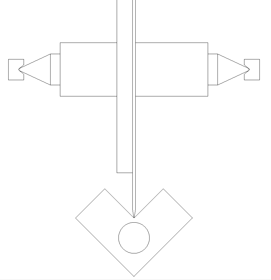
Here is my version of a "sine bar": an afternoon to build it at a 0 cost. (thanks Warrjon, I know - thanks to chinese items I became friendly with the Amazon courier - but I enjoy recycling: the depth gauge of my router gives 2/100 mm, more than enough for this task.
Hoping that this gadget could interest to anyone with curiosity to measure his realizations, or some manufacturer's claims. Both the sides height ("hinge" + depth gauge) can be changed to make positive and negative tilting.
carlo
#3528 - the measures are an average, obtained alternating the shims under the left and right support, to compensate for any deficiencies in the leveling of the base.
However the stiction is a complex phenomenon, and the simple rail tilting in my experience generates variable measurements (with heavy carriages certainly much less, but on the Lil Casey weight must be <15 gr, cartridge included). The "uphill stop" method strangely gives more uniform results.
attachment
Here is my version of a "sine bar": an afternoon to build it at a 0 cost. (thanks Warrjon, I know - thanks to chinese items I became friendly with the Amazon courier - but I enjoy recycling: the depth gauge of my router gives 2/100 mm, more than enough for this task.
Hoping that this gadget could interest to anyone with curiosity to measure his realizations, or some manufacturer's claims. Both the sides height ("hinge" + depth gauge) can be changed to make positive and negative tilting.
carlo
Attachments
Thanks Niffy, let's see if this "masterpiece" deserves your compliments. A little mod, with an adjusting screw for the left support tuning, made first leveling much faster. (attachment)
I found more or less the data previously posted - max differences + 10-15 cents, which fall within the subjectivity of the observations, or some differences of leveling, that is very critical.
At the beginning, the carriage A showed almost doubled measurements, and I could not understand why: then the irregular motion remembered me that the rail had remained all the time in the midst of the work dust. after a thoroughly cleaning everything went back to the normal.
So beware of dust: can double the friction, and frustrate the construction sophistications.
carlo
disclaimer - When posting the photos I forgot to warn that the "sine bar" tilting gives the carriage a perfectly axial thrust. So it is excellent for testing those using a radial rail (as Lil Casey), but less for conventional LT, where the force is applied by the negative shaft lever (= torque). For these, the Niffy's inverse pendulum, which allows you to apply force directly on the head shell, seems still preferable.
Attachments
Hi Carlo,
Looks good to me.
Regarding your disclaimer. The sine bar doesn't apply force at the same location that the stylus would and therefore doesn't apply the torque that would be seen in actual usage. As the frictions that we are achieving are very low the amount of torque and the modification to the loading of the bearings that result will be extremely low. The sine bar has the big advantage over the pendulum in that it also measures dynamic friction. If my hypothesis that my bearings operate purely in dynamic friction is true then this would make the sine bar method better suited to our application.
Further to your observation that at the extreme of movement on an eccentric record the force due to friction would be operating in the opposite direction to that of inertia. This could result in the peek level of cantilever displacement being less than that due to either by itself, the friction in effect damping the inertia. If this is the case then you would expect the maximum deflection of the cantilever to be greater on a perfectly concentric record than on a mildly eccentric one as only friction would be at play. (A very eccentric record would show greater deflection as inertia would again dominate).
Lately, every time I put a record on I checked to see what the level of eccentricity is. Having found a record that appeared perfectly concentric I had a good look at the deflection of the cantilever. As the displacement is very small it is difficult to be certain but the stylus did appear to be very slightly deflected to the left. On mildly eccentric records it remains more centred.
This seems totally counterintuitive.
The difference is extremely small, probably accounting for about 0.05° of defection. I have started trying to determine how the effects of inertia sum to those of friction and so far the results seem to suggest that cantilever deflection is actually less on mildly eccentric records. Who would have thought that.
The error due to the variation in groove angle due to the eccentricity still dominates on most records so tracking error will still be greater with eccentric records in most cases.
Niffy
Carlo,
Great work! You seem to be getting very low friction using Aluminum and Carbon Fiber. Nothing really hard like Tungsten Carbide. That's encouraging.
I'm about to order some Tungsten Carbide rods anyway. I'm hoping they're more straight than some other materials I've tried.
Hugh
Great work! You seem to be getting very low friction using Aluminum and Carbon Fiber. Nothing really hard like Tungsten Carbide. That's encouraging.
I'm about to order some Tungsten Carbide rods anyway. I'm hoping they're more straight than some other materials I've tried.
Hugh
..You seem to be getting very low friction using Aluminum and Carbon Fiber. Nothing really hard like Tungsten Carbide. That's encouraging.
Balls are the usual ones for bearings: don't remember if stainless or chromed - or black delrin, whith more or less the same results. delrin on anodized - steel on carbon - different materials cut resonances. In this tests always steel ones: A + C 3,5 mm - B 5,5mm. Rail is cut from commercial profiles, simply trying to find a straight 25 cm piece. (rolling + watching reflections inside)
Low friction doesn't come from my skill, construction, or materials: simply from the kind of bearing used (non recirculating linear - just 2+2 balls) + the least possible weight. And friction is not the first advantage to use it
There is an entire thread dedicated to this argument. - My Linear Tracker (a new variation perhaps?) -.
carlo
What if: of course sapphire balls on a berillium rail even better... for the weight, (my rail must be <10 gr), not for friction.
Carlo,
Great work! You seem to be getting very low friction using Aluminum and Carbon Fiber. Nothing really hard like Tungsten Carbide. That's encouraging.
I'm about to order some Tungsten Carbide rods anyway. I'm hoping they're more straight than some other materials I've tried.
Hugh
Hi Hugh,
The eBay carbide rods are terrible, I had to order a 6 to get 2 that were straight within 0.02mm. If I were doing this again I would use HSS rod.
4mm Dia 200mm Length HSS Round Shaft Rod Bar Lathe Tools Gray 5pcs 601382887694 | eBay
Hi Carlo,
Have you considered using Si3N4 balls they are about 60% lighter than chrome and far better toleranced and smoother especially grade 3
Can you post some pictures and details when you have it up and running. I for one would like to give it a try, even though I have spent weeks making the TT1 clone
Have you considered using Si3N4 balls they are about 60% lighter than chrome and far better toleranced and smoother especially grade 3
Can you post some pictures and details when you have it up and running. I for one would like to give it a try, even though I have spent weeks making the TT1 clone
Last edited:
Carbide Rods
For others, I should have added...
Centennial Carbide in the US tells me they (no longer) ship outside the US.
Hugh
Hi Hugh,
The eBay carbide rods are terrible, I had to order a 6 to get 2 that were straight within 0.02mm. If I were doing this again I would use HSS rod.
4mm Dia 200mm Length HSS Round Shaft Rod Bar Lathe Tools Gray 5pcs 601382887694 | eBay
For others, I should have added...
Centennial Carbide in the US tells me they (no longer) ship outside the US.
Hugh
Hi Niffy - The effects of eccentricities can be seen clearly (better with a macroscope) in extreme conditions: eccentricity > RIAA, excessive weight, relevant friction. Especially if one wants to see them, because unfortunately these extreme conditions are damn normal.
... but the stylus did appear to be very slightly deflected to the left. On mildly eccentric records it remains more centered.-- This seems totally counterintuitive.
When the carriage friction becomes really good, around 1mN, as you have demonstrated, the situation changes deeply: the length of the shaft has little influence, friction and inertia allow the stylus to follow the groove quite faithfully.*
... so far the results seem to suggest that cantilever deflection is actually less on mildly eccentric records. Who would have thought that.
What you say would be desirable since, unfortunately, LP eccentricity is the rule: however even this behavior has the defect of being variable, and to variations the hearing is extremely sensitive (as well as sight, we are hunters, by nature)
carlo
* If you have seen how the supports are made you will notice that, before being secured with a rubber band, the rail can slide on them easily. Imagine my wonder when, inadvertently moving the rail, the carriage (just 16 grams!) stood still in its place. Only pushing the rail slower and slower, i was able to make the carriage move synchronously.
Last edited:
Hi Warren, thanks for the Si3N4 hint. However the Harken black-delrin ones, hard enough to face hundreds of kg, weighs even less, and above all I have many as spares for their cam-cleats. (in 5 -10 years the sun damages them). However, it is not the weight of 4 balls of 3.5 mm that worries me, while it is that of the carriage + rail.
Imho it's not to worry about a rail bending of 2 cents, because your carriage - if you don't tell him - will not even notice. Seeing my carriages sensitive to a tilting of 1-2 tenths was frankly surprising, but is still ten times more.
Can you post some pictures and details when you have it up and running.
Details of what? I was hoping that the drawings and photos of parts and tests of the Lil Casey were exhaustive. If instead are those of the mk3 (if ever it will be), you'll wait for a while, since I like to work the aluminum much more than carbon, but i'll have to reduce its thickness in half in order to weigh as carbon. But how? someone says with a router, but how to get the necessary accuracy?
And consider too that tests are more useful if made before, than after.
I for one would like to give it a try,
just trow a handful of balls on the floor, and try to walk over them...
carlo
Last edited:
Cheers Carlo, I was referring the Mk3. But at my pace I might not get it built before I die.
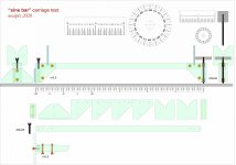
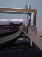
Making slow progress. Mocked up to check height. I added screws (the black cap head screws) on each end of the horizontal bar (rail support) that the rail will suspend from to allow a small amount of LTA adjustment for fine tuning. These screws have a 60deg point into a Vee brass insert. I'll cut the head off and slot the screw and add a nut to lock it down later.
I made the rail support slightly tight so it applies enough pressure so as not to need springs to load the VTA. Each end is adjustable for tilt or more precisely to level the rail with nearly 7mm adjustment. The rail support also has a hardwood core glued in to stiffen it.
I ran out of carbon fibre, so the bottom of the carriage is not yet finished. The VEE bearing wheels are far better than the bearings in my current setup, they spin for ages, very low friction.
The runout in the previous wheels was unacceptable, so these wheels are machined from a single piece of aluminium with the carbide rings an interference fit.
.
Attachments
Awesome, remarkable, Warren. "The Definitive Tonearm" could be defined by any famous manufacturer.
---
To play with my new sinebar rig, I also re-measured the JR Casey carriage (see # 2360). An attempt made after dropping an awful ball-bearings LT many years before. Not despicable but it's behavior was not up to my aspectative. However an useful experiment for me, since it drove to the radial rail concept.
total weight of the carriage (cartridge + CW incl.) = 53 gr
friction - runs with a tilt of a 0.85 height / 300mm rail. angle = 0 ° 9'44 "= 0.162 decimal --- μ = 0.0028
stiction - starts with a tilt of a 1.35 height / 300mm rail. angle = 0 ° 15'3 "= 0.251 decimal --- μ = 0.0044
The measurement of the stiction performed with the inverse pendulum (# 2605) gave 3.75 mN
those with the sinebar rig are instead: friction 1.56 mN - stiction = 2.3 mN
Certainly there are differences due the different measurement methods and subjectivity, but maybe the main difference derives from the torque: in fact 3.75 sin 36° = 2.20 (arm - 75 mm carriage 110 mm ά = 36° ca ). That's why the same carriage, used on a radial rail, traced without problems also on the mockup (# 2383)
carlo
Hope i'm not mistaking, there is nothing worse than being convinced of something.
Last edited:
Quote, Warren: exactly what I meant by the term torque - tau = r * F * sin theta - (I hope I have correctly translated the physical term coppia in Italian) see also #3564 disclaimer - and it is exactly what induced me to use a radial rail, where tau = 0
The inverse pendulum, applying force at the point where the SF of the stylus is exerted, takes tau into account, while the sine bar not. Unfortunately the pendulum has two defects - the sliding of the string on the carriage, and the subsequent dragging due to it's weight (therefore the stiction is correct, while the subsequent behavior maybe not).
It would be useful if many measured their carriage, to know which are the best solutions, not only in theory or by sensations.
carlo
what a dumb 1: there is no need to raise the sine-bar rig on right and then the left side to check if the base is horizontal, just rotate it 180°, as you do to check any bubble level.
what a dumb 2 - to level the base I've used a good laser level, measuring the alignment on the wall: a very precise method, a sin that I later discovered that the floor is not at all horizontal
Last edited:
Straight rods
Hi again warrjon,
I just received some 5mm Carbide rods from a US ebay seller called Castlebar. They seem pretty good when I roll them on a table. But now I'm wondering how you were able to check yours to be straight within 0.02mm. Did you use your Lathe for this? (I'm envious again).
Hugh
Hi Hugh,
The eBay carbide rods are terrible, I had to order a 6 to get 2 that were straight within 0.02mm. If I were doing this again I would use HSS rod.
4mm Dia 200mm Length HSS Round Shaft Rod Bar Lathe Tools Gray 5pcs 601382887694 | eBay
Hi again warrjon,
I just received some 5mm Carbide rods from a US ebay seller called Castlebar. They seem pretty good when I roll them on a table. But now I'm wondering how you were able to check yours to be straight within 0.02mm. Did you use your Lathe for this? (I'm envious again).
Hugh
- Home
- Source & Line
- Analogue Source
- DIY linear tonearm