Hi Merlin
Try reducing cart load... it will make sound more even and will pull output down also.
What cart loading are you using for the 103r ?
Good catch Ricardo, now is sounding OK with 150R as cart load. Still sounds better Salas 20dBs pre-pre battery powered than Piccolo 26dBs
")
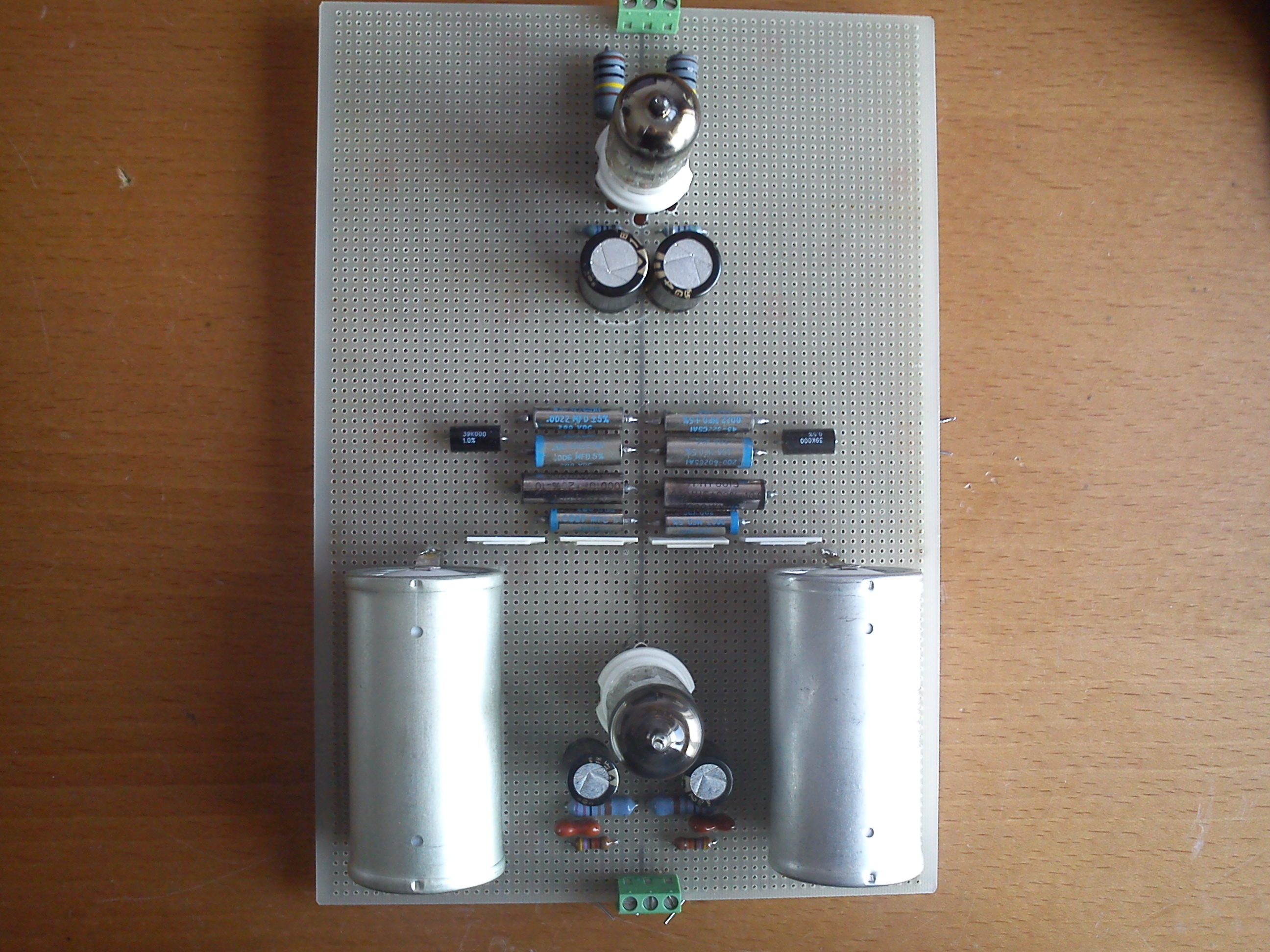
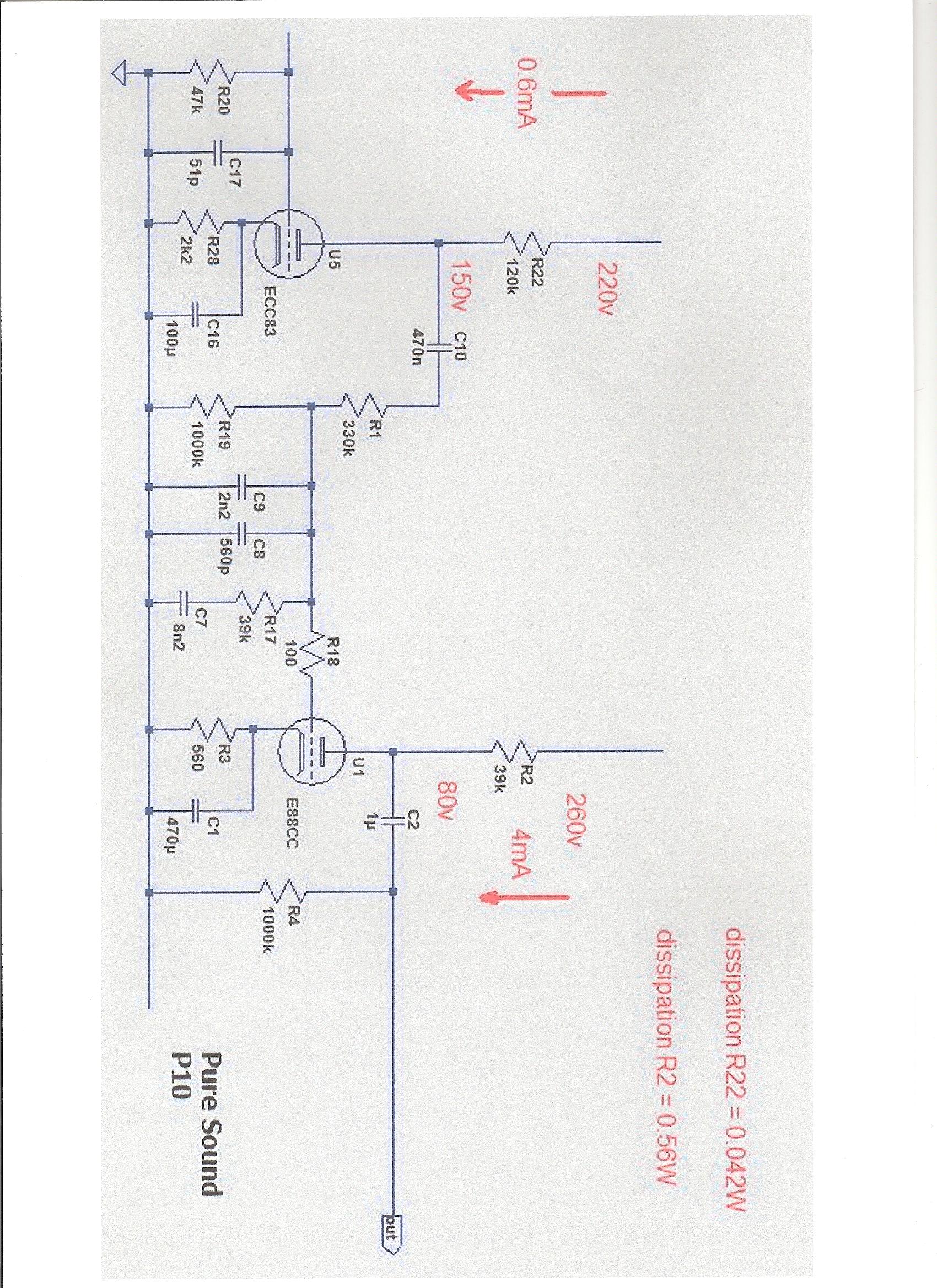
I'm open this new thread to fine tune my Puresound P10 phono RIAA, also I would like to know output impedance of first stage? schematics & real unsoldered components values as follows:
Left channel
R1 329K CADDOCK TF020R
R19 998K CADDOCK TF020R
C9+C8 .00270 paralleled .000106 = 2.806nF teflon film & aluminium foil
R17 38K9 CADDOCK TF020R
C7 .006 paralleled .0022 = 8,2nF teflon film & aluminium foil
R18 99R9 SHINKOH
Right channel
R1 329K CADDOCK TF020R
R19 999k CADDOCK TF020R
C9+C8 .00270 paralleled .000106 = 2.806nF teflon film & aluminium foil
R17 38K9 CADDOCK TF020R
C7 .006 paralleled .0022 = 8,2nF teflon film & aluminium foil
R18 99R9 SHINKOH
Any help will welcome.
Sorry to dig up an old thread....... but the caps in the riaa network look interesting, "teflon film & aluminium foil"
Could I ask what manufacturer/type they are?
Thanks
No, these are made in USA caps: I bought them in USA.
Do you know what company in the usa made then? Or is there a part number written on them?
Thx
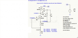
Try the jung circuit...
http://www.bartola.co.uk/valves/2015/08/31/ccs-not-everything-that-glitters-is-gold-part-i/
http://www.bartola.co.uk/valves/2015/08/31/ccs-not-everything-that-glitters-is-gold-part-i/
Could I use this IR LED in place of cathode RC bias?
https://www.mouser.es/ProductDetail/Vishay-Semiconductors/TSHF6210?qs=RzxYCzJDjPWqcTfiVxfCUQ%3D%3D
https://www.mouser.es/ProductDetail/Vishay-Semiconductors/TSHF6210?qs=RzxYCzJDjPWqcTfiVxfCUQ%3D%3D
IR Leds are normally noisy unless you run them at high currents ... why do you need this type of led ?
Noise measurements for LEDs and zener diodes
--------------------------------------------
(C) Christer at DiyAudio.com
You are allowed to copy and use this information for your personal and non-commercial use.
v. 1.3 Added more devices. Introductory text not changed to reflect this.
v. 1.4. Added new experiment (number 2) at the end.
EXPERIMENT 1
============
DESCRIPTION OF TEST RIG
-----------------------
The test rig uses three current sources of approx. 1, 5 and 20 mA built using low-noise BJTs (BC559) to feed the device under test (DUT) alternatingly. The noise was measured using two op amps in in non-inverting configuration cascaded, both having a gain of 34, making a gain of 1156 in total. The first op amp is a very-low-noise model (LT1115) and uses a gain resistor of only 10 Ohms in the feedback network. The gain resistor is thus 330 Ohms which works since the opamp is only expected to output very low-level signals. The second op amp is a low-noise type (NE5534) with gain and feedback resistors of 100 Ohms and 3.3 kOhms. The output was measured using a PC soundcard (Creative Audigy LS in 16-bit 44.1 kHz mode). Each measurement consists of a 10 second capture of the soundcard input and the RMS value for this 10 s. signal was computed. The program was calibrated (using a sine wave and an oscilloscope) to give aprroximately correct voltage readings and all measurements were divided by 1156 to give the equivalent input RMS noise at the first op amp, ie. at the DUT. No extra filters except what is on the soundcard were used.
TEST METHOD
-----------
A spectrum of LED types ranging from IR to blue and of approximately the same type were measured. All LEDS were selected to have an max If of at least 20 mA, since this current was used in the test. Further four 0.5W types of zener diodes were tested, two of them (5.6 and 6.8 V) were deliberately selected close to each other but such that the 5.6 V diode should be expected to have true zener breakdown and the 6.8 V one to have avalanche breakdown. The other two were selected to be far away from this "transition region". Two 1.3W zeners were also tested to see how the power rating affects noise figures.
For each type of DUT, two devices (denoted #1 and #2 and presumably from the same batch) were tested at the three test currents 1, 5 and 20 mA and the equivalent noise at the DUT was measured and calculated as described above. For each combination of device and current, five 10-second measurements were made.
For reference, the voltage drop at each test current was also measured for one device of each type.
MEASUREMENTS
------------
EXPERIMENT 2
============
TEST RIG
--------
Almost the same set up as in experiment 1, but one single current source was used with a 500 Ohm trim pot in series with 10 Ohm as emitter resistor.
TEST METHOD
-----------
One or two devices of selected LED types were tested at currents 2, 4, 6 and 8 mA with the purpose of spotting a tendency towards a noise optimum at some current. Depending on these results, measurements at certain other currents were sometimes added. In those cases where two devices were tested, device numbers may be swapped compared to experiment 1. Voltage drop was added to the tables in these measurements. As previously, five rms noise readings over 10 s each were taken.
MEASUREMENTS
------------
Noise measurements for LEDs and zener diodes
--------------------------------------------
(C) Christer at DiyAudio.com
You are allowed to copy and use this information for your personal and non-commercial use.
v. 1.3 Added more devices. Introductory text not changed to reflect this.
v. 1.4. Added new experiment (number 2) at the end.
EXPERIMENT 1
============
DESCRIPTION OF TEST RIG
-----------------------
The test rig uses three current sources of approx. 1, 5 and 20 mA built using low-noise BJTs (BC559) to feed the device under test (DUT) alternatingly. The noise was measured using two op amps in in non-inverting configuration cascaded, both having a gain of 34, making a gain of 1156 in total. The first op amp is a very-low-noise model (LT1115) and uses a gain resistor of only 10 Ohms in the feedback network. The gain resistor is thus 330 Ohms which works since the opamp is only expected to output very low-level signals. The second op amp is a low-noise type (NE5534) with gain and feedback resistors of 100 Ohms and 3.3 kOhms. The output was measured using a PC soundcard (Creative Audigy LS in 16-bit 44.1 kHz mode). Each measurement consists of a 10 second capture of the soundcard input and the RMS value for this 10 s. signal was computed. The program was calibrated (using a sine wave and an oscilloscope) to give aprroximately correct voltage readings and all measurements were divided by 1156 to give the equivalent input RMS noise at the first op amp, ie. at the DUT. No extra filters except what is on the soundcard were used.
TEST METHOD
-----------
A spectrum of LED types ranging from IR to blue and of approximately the same type were measured. All LEDS were selected to have an max If of at least 20 mA, since this current was used in the test. Further four 0.5W types of zener diodes were tested, two of them (5.6 and 6.8 V) were deliberately selected close to each other but such that the 5.6 V diode should be expected to have true zener breakdown and the 6.8 V one to have avalanche breakdown. The other two were selected to be far away from this "transition region". Two 1.3W zeners were also tested to see how the power rating affects noise figures.
For each type of DUT, two devices (denoted #1 and #2 and presumably from the same batch) were tested at the three test currents 1, 5 and 20 mA and the equivalent noise at the DUT was measured and calculated as described above. For each combination of device and current, five 10-second measurements were made.
For reference, the voltage drop at each test current was also measured for one device of each type.
MEASUREMENTS
------------
Code:
All values are RMS values, five measurements for each case.

Idle noise:
----------------------------------------------------
Measured idle noise of amplifier with grounded input:
0.19 0.19 0.19 0.19 0.18 uV
(The theoretical max value was calculated to 0.16 uV for
20kHz bandwidth  and 0.22 uB for 40 kHz bandwidth).

Measured idle noise of amplifier with 100 Ohm source resistor:
0.26 0.25 0.24 0.26 0.26 uV
(The theoretical max value was calculated to 0.20 uV for
20kHz bandwidth  and 0.28 uB for 40 kHz bandwidth).


Diodes:
---------------------------------------------------

1N4148 (unknown brand):
#1 @ 1mA:  0.28 0.28 0.28 0.27 0.27 uV
#1 @ 5mA:  0.25 0.25 0.22 0.22 0.22 uV
#1 @ 20mA: 0.24 0.21 0.22 0.25 0.23 uV
#2 @ 1mA:  0.38 0.27 0.28 0.26 0.29 uV  (Vf = 0.57 V)
#2 @ 5mA:  0.23 0.22 0.23 0.23 0.23 uV  (Vf = 0.65 V)
#2 @ 20mA: 0.23 0.21 0.21 0.21 0.24 uV  (Vf = 0.75 V)

1N4004 (unknown brand):
#1 @ 1mA:  0.31 0.29 0.29 0.29 0.29 uV
#1 @ 5mA:  0.26 0.24 0.26 0.26 0.25 uV
#1 @ 20mA: 0.27 0.23 0.23 0.24 0.23 uV
#2 @ 1mA:  0.29 0.25 0.25 0.27 0.26 uV  (Vf = 0.55 V)
#2 @ 5mA:  0.29 0.24 0.25 0.23 0.23 uV  (Vf = 0.62 V)
#2 @ 20mA: 0.23 0.23 0.22 0.21 0.22 uV  (Vf = 0.71 V)


LEDs:
----------------------------------------------------
Brand is Everlight unless otherwise stated.

IR204/P1 (IR):
#1 @ 1mA:  3.7  3.7  3.7  3.7  3.7  uV
#1 @ 5mA:  0.67 0.66 0.65 0.66 0.66 uV
#1 @ 20mA: 0.24 0.23 0.24 0.23 0.23 uV
#2 @ 1mA:  3.8  3.8  3.7  3.7  3.7  uV  (Vf = 1.05 V)
#2 @ 5mA:  0.65 0.64 0.64 0.64 0.64 uV  (Vf = 1.11 V)
#2 @ 20mA: 0.24 0.25 0.23 0.24 0.22 uV  (Vf = 1.17 V)

EL202HD (red):
#1 @ 1mA:  0.31 0.32 0.31 0.31 0.32 uV
#1 @ 5mA:  0.26 0.26 0.27 0.27 0.27 uV
#1 @ 20mA: 0.39 0.36 0.37 0.36 0.37 uV
#2 @ 1mA:  0.39 0.37 0.38 0.38 0.35 uV  (Vf = 1.82 V)
#2 @ 5mA:  0.32 0.30 0.30 0.30 0.31 uV  (Vf = 1.89 V)
#2 @ 20mA: 0.41 0.40 0.41 0.41 0.46 uV  (Vf = 2.09 V)

EL1254HD/T2 (red):
#1 @ 1mA:  0.36 0.35 0.35 0.34 0.35 uV
#1 @ 5mA:  0.30 0.29 0.31 0.32 0.30 uV
#1 @ 20mA: 0.51 0.56 0.54 0.55 0.53 uV
#2 @ 1mA:  0.53 0.42 0.39 0.41 0.40 uV  (Vf = 1.82 V)
#2 @ 5mA:  0.30 0.30 0.31 0.29 0.29 uV  (Vf = 1.90 V)
#2 @ 20mA: 0.42 0.42 0.42 0.43 0.43 uV  (Vf = 2.17 V)

L934ID/B (red):
#1 @ 1mA:  0.29 0.28 0.28 0.27 0.28 uV
#1 @ 5mA:  0.27 0.24 0.24 0.23 0.24 uV
#1 @ 20mA: 0.39 0.32 0.29 0.48 0.29 uV
#2 @ 1mA:  0.34 0.28 0.28 0.28 0.27 uV  (Vf = 1.64 V)
#2 @ 5mA:  0.24 0.24 0.25 0.24 0.25 uV  (Vf = 1.72 V)
#2 @ 20mA: 0.30 0.25 0.27 0.30 0.28 uV  (Vf = 1.89 V)
(Brand is Kingbright)

EL204ID (red-orange):
#1 @ 1mA:  0.31 0.30 0.31 0.31 0.31 uV
#1 @ 5mA:  0.25 0.26 0.26 0.26 0.24 uV
#1 @ 20mA: 0.41 0.41 0.48 0.40 0.41 uV
#2 @ 1mA:  0.35 0.31 0.29 0.30 0.32 uV  (Vf = 1.64 V)
#2 @ 5mA:  0.25 0.26 0.27 0.26 0.30 uV  (Vf = 1.74 V)
#2 @ 20mA: 0.40 0.40 0.39 0.40 0.41 uV  (Vf = 1.90 V)

EL204YD (yellow):
#1 @ 1mA:  0.42 0.30 0.29 0.29 0.28 uV
#1 @ 5mA:  0.28 0.26 0.25 0.33 0.27 uV
#1 @ 20mA: 0.42 0.39 0.39 0.40 0.40 uV
#2 @ 1mA:  0.31 0.30 0.31 0.30 0.31 uV  (Vf = 1.78 V)
#2 @ 5mA:  0.28 0.47 0.28 0.26 0.25 uV  (Vf = 1.87 V)
#2 @ 20mA: 0.34 0.34 0.35 0.34 0.34 uV  (Vf = 2.02 V)

EL204GD (green):
#1 @ 1mA:  0.68 0.50 0.50 0.47 0.46 uV
#1 @ 5mA:  0.35 0.30 0.28 0.28 0.29 uV
#1 @ 20mA: 0.36 0.35 0.35 0.35 0.35 uV
#2 @ 1mA:  0.46 0.46 0.44 0.44 0.41 uV  (Vf = 1.82 V)
#2 @ 5mA:  0.36 0.33 0.32 0.33 0.32 uV  (Vf = 1.92 V)
#2 @ 20mA: 0.39 0.40 0.39 0.41 0.40 uV  (Vf = 2.12 V)

EL1254GD/T2 (green):
#1 @ 1mA:  0.36 0.36 0.34 0.33 0.34 uV  (Vf = 1.84 V)
#1 @ 5mA:  0.40 0.40 0.38 0.41 0.40 uV  (Vf = 1.96 V)
#1 @ 20mA: 1.8  1.9  1.9  1.9  2.1  uV  (Vf = 2.20 V)
#2 @ 1mA:  0.46 0.41 0.36 0.37 0.39 uV  (Vf = 1.82 V)
#2 @ 5mA:  0.41 0.42 0.35 0.34 0.31 uV  (Vf = 1.93 V)
#2 @ 20mA: 0.48 0.50 0.48 0.50 0.51 uV  (Vf = 2.27 V)
(Measured Vf of both devices for potential correlation
with differing noise figs. at 20 mA. Obviously no
such correlation found.)

EL204UBD (blue):
#1 @ 1mA:  4.6 4.5 4.6 4.5 4.6 uV
#1 @ 5mA:  3.2 3.2 3.2 3.2 3.2 uV
#1 @ 20mA: 2.8 2.8 2.7 2.7 2.7 uV
#2 @ 1mA:  4.4 4.4 4.3 4.2 4.3 uV  (Vf = 3.26 V)
#2 @ 5mA:  3.1 3.2 3.2 3.1 3.2 uV  (Vf = 3.44 V)
#2 @ 20mA: 2.9 2.8 2.8 2.8 2.7 uV  (Vf = 3.69 V)


Zeners:
---------------------------------------------------------
(All zeners of brand Temic.)

BZX55/C2V7 (0.5W 2.7V):
#1 @ 1mA:  1.1  1.1  1.1  1.1  1.1  uV
#1 @ 5mA:  1.0  0.88 0.85 0.86 0.87 uV
#1 @ 20mA: 1.0  0.81 0.72 0.72 1.1  uV
#2 @ 1mA:  1.2  1.1  1.1  1.1  1.1  uV  (Vr = 2.03 V)
#2 @ 5mA:  0.91 0.88 0.87 0.86 0.85 uV  (Vr = 2.50 V)
#2 @ 20mA: 1.1  0.80 0.77 0.73 0.71 uV  (Vr = 3.02 V)

BCX55/C3V9 (0.5W 3.9V):
#1 @ 1mA:  1.7  1.8  1.7  1.6  1.6  uV
#1 @ 5mA:  1.1  1.1  1.1  1.2  1.1  uV
#1 @ 20mA: 0.94 9.76 0.84 0.79 0.77 uV
#2 @ 1mA:  1.6  1.6  1.6  1.5  1.6  uV  (Vr = 3.17 V)
#2 @ 5mA:  1.2  1.1  1.1  1.1  1.1  uV  (Vr = 3.83 V)
#2 @ 20mA: 0.97 0.78 0.86 0.76 0.77 uV  (Vr = 4.45 V)

BZX55/C5V6 (0.5W 5.6V):
#1 @ 1mA:  5.3  5.3  5.3  5.3  5.3  uV
#1 @ 5mA:  2.9  2.9  2.9  2.9  2.9  uV
#1 @ 20mA: 1.7  1.6  1.6  1.6  1.6  uV
#2 @ 1mA:  5.3  5.3  5.3  5.3  5.3  uV  (Vr = 5.68 V)
#2 @ 5mA:  2.9  2.9  2.9  2.9  2.9  uV  (Vr = 5.77 V)
#2 @ 20mA: 1.8  1.6  1.6  1.6  1.6  uV  (Vr = 5.81 V)

BZX55/C6V2 (0.5W 6.2V):
#1 @ 1mA:  9.0 8.9 8.9 8.9 8.9 uV
#1 @ 5mA:  3.7 3.6 3.6 3.6 3.6 uV
#1 @ 20mA: 1.7 1.6 1.6 1.6 1.6 uV
#2 @ 1mA:  9.4 9.4 9.3 9.3 9.3 uV  (Vr = 6.31 V)
#2 @ 5mA:  3.7 3.7 3.8 3.7 3.7 uV  (Vr = 6.33 V)
#2 @ 20mA: 2.6 1.8 1.8 1.8 1.7 uV  (Vr = 6.38 V)


BZX55/C6V8 (0.5W 6.8V):
#1 @ 1mA:  16   16   16   16   16   uV
#1 @ 5mA:  21   21   21   21   21   uV
#1 @ 20mA:  5.8  5.5  5.5  5.5  5.6 uV
#2 @ 1mA:  25   25   25   25   25   uV  (Vr = 6.93 V)
#2 @ 5mA:  13   13   13   13   13   uV  (Vr = 6.96 V)
#2 @ 20mA:  4.6  4.7  4.5  4.5  4.4 uV  (Vr = 7.00 V)
(Rechecked both devices due to their inconsistent
behaviour for 1 and 5mA).

BCX55/C7V5 (0.5W 7.5V):
#1 @ 1mA:  116 116 116 116 119 uV
#1 @ 5mA:   50  50  50  50  50 uV
#1 @ 20mA:  25  24  24  24  24 uV
#2 @ 1mA:  118 117 116 117 116 uV  (Vr = 7.58 V)
#2 @ 5mA:   50  50  50  50  50 uV  (Vr = 7.62 V)
#2 @ 20mA:  18  18  18  18  18 uV  (Vr = 7.72 V)
(The high readings seem to correlate with scope
readings. These devices were possibly of a
different brand.)

8.2V (unknown brand, probably 0.5W):
#1 @ 1mA:  108 109 109 109 109 uV
#1 @ 5mA:   49  49  48  48  48 uV
#1 @ 20mA:  15  15  14  14  14 uV
#2 @ 1mA:  108 107 107 106 106 uV  (Vr = 7.93 V)
#2 @ 5mA:   39  39  39  39  39 uV  (Vr = 7.97 V)
#2 @ 20mA:  14  13  13  13  13 uV  (Vr = 8.10 V)

BZX55/C12   (0.5W 12V):
#1 @ 1mA:  0.35 0.37 0.37 0.39 0.39 uV
#1 @ 5mA:  0.30 0.28 0.28 0.28 0.30 uV
#1 @ 20mA: 0.24 0.25 0.25 0.26 0.25 uV
#2 @ 1mA:  0.32 0.33 0.32 0.33 0.32 uV  (Vr = 11.32 V)
#2 @ 5mA:  0.26 0.26 0.27 0.32 0.26 uV  (Vr = 11.37 V)
#2 @ 20mA: 0.25 0.26 0.28 0.24 0.30 uV  (vr = 11.42 V)

BZX85/C2V7 (1.3W 2.7V):
#1 @ 1mA:  0.77 0.77 0.77 0.77 0.76 uV
#1 @ 5mA:  0.62 0.61 0.63 0.61 0.60 uV
#1 @ 20mA: 0.55 0.55 0.54 0.55 0.55 uV
#2 @ 1mA:  0.78 0.78 0.78 0.78 0.78 uV  (Vr = 1.30 V)
#2 @ 5mA:  0.62 0.62 0.61 0.62 0.62 uV  (Vr = 1.61 V)
#2 @ 20mA: 0.57 0.56 0.57 0.56 0.56 uV  (Vr = 1.92 V)

BZX85/C12 (1.3W 12V):
#1 @ 1mA:  0.49 0.53 0.48 0.50 0.52 uV
#1 @ 5mA:  0.54 0.55 0.58 0.46 0.48 uV
#1 @ 20mA: 0.44 0.35 0.38 0.36 0.33 uV
#2 @ 1mA:  0.42 0.43 0.46 0.48 0.41 uV  (Vr = 9.84 V)
#2 @ 5mA:  0.40 0.35 0.35 0.37 0.29 uV  (Vr = 9.89 V)
#2 @ 20mA: 0.34 0.33 0.31 0.30 0.31 uV  (Vr = 9.94 V)


Miscellaneous:
-----------------
TL431 (Ref tied to cathode to work as 2.5V zener diode):
#1 @ 1mA:  20 20 20 20 20  uV
#1 @ 5mA:  20 20 20 20 20  uV
#1 @ 20mA: 20 20 20 20 20  uV
#2 @ 1mA:  20 20 20 20 20  uV
#2 @ 5mA:  20 20 20 20 20  uV
#2 @ 20mA: 20 20 20 20 20  uV
(No cheating, the measurements actually were so
consistent.)

TL431 (strapped as 5V ref. using two 1kOhm resistors):
#1 @ 1mA:   3.2  3.2  3.2  3.2  3.2  uV
#1 @ 5mA:  41   41   41   41   41    uV
#1 @ 20mA: 42   42   42   42   42    uV
#2 @ 1mA:   3.2  3.3  3.2  3.3  3.3  uV
#2 @ 5mA:  41   41   41   41   41    uV
#2 @ 20mA: 42   42   42   42   42    uV

BC549 BE diode forward biased:
#1 @ 1mA:  0.24 0.24 0.24 0.24 0.24  uV
#1 @ 5mA:  0.22 0.23 0.22 0.24 0.23  uV
#1 @ 20mA: 0.22 0.21 0.20 0.22 0.20  uV
#2 @ 1mA:  0.23 0.23 0.25 0.24 0.24  uV  (Vf = 0.73 V)
#2 @ 5mA:  0.23 0.23 0.23 0.23 0.22  uV  (Vf = 0.78 V)
#2 @ 20mA: 0.21 0.22 0.21 0.20 0.21  uV  (Vf = 0.86 V)

BC549 BE diode reverse biased:
#1 @ 1mA:  56   59   59   56   57   uV
#1 @ 5mA:   8.1  8.2  8.3  8.4  8.4 uV
#1 @ 20mA:  4.7  4.7  4.8  4.9  4.8 uV
#2 @ 1mA:  60   56   54   52   50   uV  (Vr = 8.33 V)
#2 @ 5mA:  18   17   16   15   14   uV  (Vr = 8.39 V)
#2 @ 20mA:  4.8  4.8  4.8  4.9  4.8 uV  (Vr = 8.68 V)
EXPERIMENT 2
============
TEST RIG
--------
Almost the same set up as in experiment 1, but one single current source was used with a 500 Ohm trim pot in series with 10 Ohm as emitter resistor.
TEST METHOD
-----------
One or two devices of selected LED types were tested at currents 2, 4, 6 and 8 mA with the purpose of spotting a tendency towards a noise optimum at some current. Depending on these results, measurements at certain other currents were sometimes added. In those cases where two devices were tested, device numbers may be swapped compared to experiment 1. Voltage drop was added to the tables in these measurements. As previously, five rms noise readings over 10 s each were taken.
MEASUREMENTS
------------
Code:
EL202HD (red):
#1  1.5mA 1.86V Noise: 0.32 0.34 0.30 0.31 0.34 uV
#1  2.0mA 1.87V Noise: 0.31 0.30 0.31 0.31 0.31 uV
#1  3.0mA 1.90V Noise: 0.30 0.29 0.29 0.27 0.28 uV
#1  4.0mA 1.92V Noise: 0.28 0.28 0.28 0.27 0.27 uV
#1  5.0mA 1.94V Noise: 0.30 0.28 0.28 0.28 0.29 uV
#1  6.0mA 1.96V Noise: 0.30 0.30 0.28 0.28 0.29 uV
#1  8.0mA 1.99V Noise: 0.30 0.33 0.32 0.30 0.31 uV
#1 10.0mA 2.03V Noise: 0.71 0.68 0.66 0.63 0.62 uV

#2  2.0mA 1.88V Noise: 0.35 0.28 0.28 0.28 0.28 uV
#2  3.0mA 1.90V Noise: 0.28 0.29 0.26 0.28 0.27 uV
#2  4.0mA 1.92V Noise: 0.27 0.28 0.27 0.27 0.27 uV
#2  5.0mA 1.94V Noise: 0.28 0.27 0.27 0.27 0.26 uV
#2  6.0mA 1.95V Noise: 0.27 0.28 0.26 0.26 0.26 uV
#2  8.0mA 1.98V Noise: 0.31 0.30 0.30 0.32 0.30 uV

L934ID/B (red):
#1  2.0mA 1.70V Noise: 0.28 0.25 0.28 0.25 0.27 uV
#1  4.0mA 1.75V Noise: 0.43 0.27 0.25 0.27 0.26 uV
#1  5.0mA 1.76V Noise: 0.39 0.25 0.25 0.25 0.24 uV
#1  6.0mA 1.78V Noise: 0.27 0.31 0.25 0.27 0.25 uV
#1  8.0mA 1.80V Noise: 0.34 0.31 0.30 0.30 0.32 uV

EL204ID (orange-red):
#1  2.0mA 1.71V Noise: 0.42 0.31 0.27 0.27 0.27 uV
#1  4.0mA 1.76V Noise: 0.30 0.32 0.32 0.29 0.27 uV
#1  5.0mA 1.78V Noise: 0.27 0.26 0.26 0.28 0.27 uV
#1  6.0mA 1.80V Noise: 0.28 0.27 0.27 0.28 0.43 uV
#1  7.0mA 1.82V Noise: 0.31 0.29 0.27 0.30 0.28 uV
#1  8.0mA 1.83V Noise: 0.60 0.35 0.36 0.35 0.33 uV

#2  2.0mA 1.71V Noise: 0.26 0.34 0.28 0.33 0.30 uV
#2  4.0mA 1.76V Noise: 0.27 0.26 0.28 0.62 0.40 uV
#2  5.0mA 1.78V Noise: 0.37 0.26 0.37 0.27 0.25 uV
#2  6.0mA 1.80V Noise: 0.29 0.28 0.27 0.26 0.26 uV
#2  7.0mA 1.81V Noise: 0.30 0.35 0.44 0.28 0.32 uV
#2  8.0mA 1.82V Noise: 0.40 0.35 0.36 0.32 0.35 uV

EL204YD (yellow):
#1  1.5mA 1.83V Noise: 0.32 0.31 0.41 0.31 0.28 uV
#1  2.0mA 1.85V Noise: 0.26 0.26 0.26 0.60 0.26 uV
#1  3.0mA 1.88V Noise: 0.26 0.28 0.25 0.28 0.24 uV
#1  4.0mA 1.90V Noise: 0.30 0.25 0.26 0.26 0.24 uV
#1  5.0mA 1.92V Noise: 0.28 0.28 0.28 0.26 0.27 uV
#1  6.0mA 1.93V Noise: 0.29 0.27 0.27 0.27 0.28 uV
#1  8.0mA 1.96V Noise: 0.31 0.31 0.31 0.32 0.32 uV

EL204GD (green):
#1  2.0mA 1.89V Noise: 0.39 0.36 1.41 0.36 0.36 uV
#1  4.0mA 1.95V Noise: 0.48 0.41 0.34 0.34 0.32 uV
#1  5.0mA 1.97V Noise: 0.33 0.33 0.32 0.31 0.31 uV
#1  6.0mA 1.99V Noise: 0.30 0.31 0.30 0.29 0.30 uV
#1  7.0mA 2.02V Noise: 0.33 0.32 0.35 0.31 0.30 uV
#1 8.0mA 2.04V Noise: 0.34 0.35 0.33 0.32 0.31 uVIs recomended by Salas for Itch.
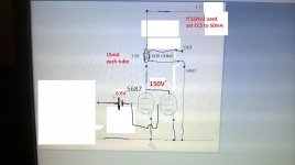
I tried in my 5687 headphone amp in place SSHV2 with pasive CRC using BG 220uF 350V 5687 headphone amp and sounds wonderful, thanks to point me the schematic Ricardo. I believe quality & value C1 is critical for best SQ.
I tried in my 5687 headphone amp in place SSHV2 with pasive CRC using BG 220uF 350V 5687 headphone amp and sounds wonderful, thanks to point me the schematic Ricardo. I believe quality & value C1 is critical for best SQ.
Attachments
- Status
- This old topic is closed. If you want to reopen this topic, contact a moderator using the "Report Post" button.
- Home
- Source & Line
- Analogue Source
- Puresound P10 RIAA