Carsten Witt YGL92S PCB with mounting holes : DC filter for SMPS wall warts
The PCB named YGL92S and/or YGL92S-A is by Carsten Witt . It is a SMPS DC inline filter PCB with four mounting holes. These holes allow you to securely fasten the PCB to a chassis, for example using M3 nuts and bolts.
You can freely download its Gerber CAD files from post #407 of this thread. Send these Gerber files to a PCB fab and have some boards made for you.
An excellent list of PCB fabs, including up-to-the-minute price quotes, is available at the website www dot pcbshopper dot com .
Finally able to post an update - my boards that should have arrived in December got to me yesterday.... a combination of DHL mis-delivering first time round and Brexit messing up deliveries from Germany for a while.
Anyway, built the first filter for use on my USB DAC, I used Wurth 744772022 inductors as the one's in the original BOM were unavailable at time of ordering (electrical specs below). I've tried to capture the waveforms on my scope, sorry the picture's not great, I think this is at the limits of what it can resolve - this is 5mV/division
I added the filter on a spare lead I had so I could A/B between the original and the filtered lead easily. Listening impressions are that the filter has made the sound a bit more focussed, transients are sharper and the placement of instruments in the soundstage is clearer. I know it's subjective (and I can't do blind testing cos it's me swapping the cables") ) but I'm happy with the improvement
) but I'm happy with the improvement
Thanks Mark.
Quick question - the original lead to the DAC is better quality but it has a large ferrite molded around the DAC end - if I swap the filter to this lead will the ferrite mess things up?


Anyway, built the first filter for use on my USB DAC, I used Wurth 744772022 inductors as the one's in the original BOM were unavailable at time of ordering (electrical specs below). I've tried to capture the waveforms on my scope, sorry the picture's not great, I think this is at the limits of what it can resolve - this is 5mV/division
I added the filter on a spare lead I had so I could A/B between the original and the filtered lead easily. Listening impressions are that the filter has made the sound a bit more focussed, transients are sharper and the placement of instruments in the soundstage is clearer. I know it's subjective (and I can't do blind testing cos it's me swapping the cables
) but I'm happy with the improvement Thanks Mark.
Quick question - the original lead to the DAC is better quality but it has a large ferrite molded around the DAC end - if I swap the filter to this lead will the ferrite mess things up?
....Anyway, built the first filter for use on my USB DAC, I used Wurth 744772022 inductors as the one's in the original BOM were unavailable at time of ordering (electrical specs below).....
Since the Wurth 744772022 inductor has a SRF ~ 75.5MHz, maybe consider a 1100 ohm damping resistor
The original 652-RLB0912-2R2ML inductor has 65MHz SRF uses a 953 ohm damping resistor.
Yes, the measurements were taken under load with the DAC connected. I don't know the details of what kind of load this represents, it's an ODAC coupled to the O2 Headphone amp. The USB power only supplies the ODAC card; the amp has a separate supply. I couldn't detect any voltage drop across the filter with my DMM showing 5.04V on input and output.
I couldn't detect any voltage drop across the filter with my DMM showing 5.04V on input and output.
Then the arithmetic carefully explained in post #473 predicts that, for your particular wall-wart and your particular ODAC, you can daisy-chain at least 4 of those noise filters in series between your wall wart and your ODAC. Then your HF noise attenuation will be raised to the fourth power(!) since
attenuation of 1 filter = "A"
attenuation of 4 filters in series = A x A x A x A = (A raised to the power 4)
Although possible, the daisy-chain idea may or may not not align with your sense of engineering elegance.
_
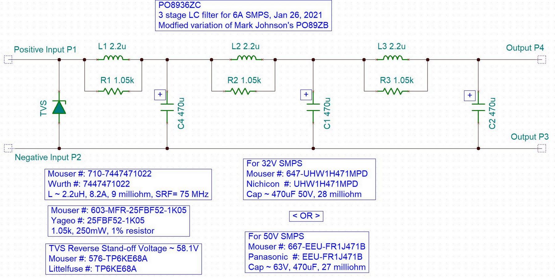
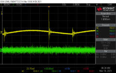
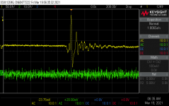
I finally got a decent scope photo of the noise from input and output of the experimental design 3 stage filter for 36V 6A applications, previously posted here: https://www.diyaudio.com/forums/ana...eamps-hpa-korg-nutube-etc-40.html#post6512950
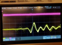
The yellow trace is from a a cheap 32V 3A brick and the purple trace is the output of the filter. The power supply produces a wide frequency spectrum of noise, but the repetitive largest spike is shown in the photo. I need to do more measurements, maybe with a 1x probe, but it was the first evening with a new scope.
The yellow trace is from a a cheap 32V 3A brick and the purple trace is the output of the filter. The power supply produces a wide frequency spectrum of noise, but the repetitive largest spike is shown in the photo. I need to do more measurements, maybe with a 1x probe, but it was the first evening with a new scope.
Attachments
In the "For What It's Worth Department" cap wise?
UHE series from Nichicon is advertised as being Miniature Sized, Low Impedance, and High Reliability. Size works, V50 x uF 470 is 10 x 31.5. Rated for 4000 to 10,000 hours while ripple is at 1690. Just had 40 show up today. Will try and get a couple assembled and pic's up late tomorrow...
UHE series from Nichicon is advertised as being Miniature Sized, Low Impedance, and High Reliability. Size works, V50 x uF 470 is 10 x 31.5. Rated for 4000 to 10,000 hours while ripple is at 1690. Just had 40 show up today. Will try and get a couple assembled and pic's up late tomorrow...
Last edited:
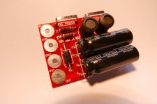
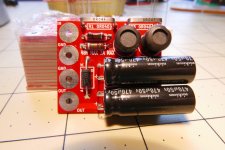
Couple pic’s, bad light temp. incandescent… sorry.
Well they (the UHE’s) are rather lengthy & rather heavy but do fit hence the recommendation per Nichicons spec. sheets deferring to UHW’s due to their favorable size compatibility. Price wise they’re comparable. The all important performance numbers will have to wait until we get back to civilization and my bench and equipment. We’re hiding out in the Blue Ridge’s till this is all over. Going off spec. sheets is one thing but what counts, for me at least, is most importantly what do they sound like? Was able to locate & ordered 37 UHW’s from Poland.
Huge Thanks to Mr. Mark Johnston for all the time, knowledge and effort.
Attachments
A majority of listening evaluations / reviews of the SMPS filter, posted here anyway, are quite positive. There have been one or two "very little change / no change to the sound" evaluations. And, if I remember correctly, not one single negative review, where the filter degraded the sound.
A couple brave souls even connected N>1 of the filters in a daisy chain series arrangement, filtering the already-filtered DC, and reported there indeed WAS additional (but small) improvement. Did it "really" sound better? Was it only "expectation bias"? Maybe the answer is, if it feels good then do it.
A couple brave souls even connected N>1 of the filters in a daisy chain series arrangement, filtering the already-filtered DC, and reported there indeed WAS additional (but small) improvement. Did it "really" sound better? Was it only "expectation bias"? Maybe the answer is, if it feels good then do it.
For those who use the Carsten Witt SMPS filter PCB [ID is YGL92S-A], see post #407, you may want to know its physical size. Knowing this can help you plan a mounting strategy within an enclosure. I recently sent the YGL92S-A Gerber files to a PCB fab, and got back 100 finished PCBoards this afternoon. Measuring one of them with a $10 micrometer, I believe that
I'd encourage ALL diyAudio members to order PCBs from a fab at least once. It's a valuable and modern skill, which will become more and more necessary as the hobby evolves and grows.
However: for those who prefer to pay extra and wait longer, in exchange for the convenience of NOT learning how to order PCBs, I will sell you some of mine. I've intentionally chosen a price, and a quantity, and a delay which are all worse than what you'd get if you ordered boards yourself from a PCB fab. But hey, if you don't mind the extra money and the extra wait and the extra boards: I can help you.
The ONLY thing I am offering is:
You might say to yourself, "Shoot dang; maybe I'll wait 3 or 6 months to see whether these PCBs eventually become products at the diyAudio Store." It's not a ridiculous idea at all, and it might save you a significant fraction of $20.
PCB edge-to-edge size is 53mm X 35mm
Mounting hole center-to-center distance is 47mm X 30mm
Mounting hole center-to-center distance is 47mm X 30mm
I'd encourage ALL diyAudio members to order PCBs from a fab at least once. It's a valuable and modern skill, which will become more and more necessary as the hobby evolves and grows.
However: for those who prefer to pay extra and wait longer, in exchange for the convenience of NOT learning how to order PCBs, I will sell you some of mine. I've intentionally chosen a price, and a quantity, and a delay which are all worse than what you'd get if you ordered boards yourself from a PCB fab. But hey, if you don't mind the extra money and the extra wait and the extra boards: I can help you.
The ONLY thing I am offering is:
* Shipment to USA addresses only; nothing that requires a customs form. That means no shipments to Guam or American Virgin Islands etc.
* Ten PCBs for $20.00. Ten is the only quantity I will sell. 5? no. 20? no.
* Payment by PayPal only.
* I will put your parcel in the USPS mail, 15 days after I receive your money. PCB fabs are faster but hey, you've chosen to pay for convenience, not speed.
* PM me your ship-to address, exactly as you want it to appear on the parcel, I'll PM you my PayPal ID. You send me $20 on PayPal, I send you ten PCBs.
You might say to yourself, "Shoot dang; maybe I'll wait 3 or 6 months to see whether these PCBs eventually become products at the diyAudio Store." It's not a ridiculous idea at all, and it might save you a significant fraction of $20.
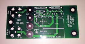
Last week I edited the PO89ZB printed circuit layout, and added a couple of BNC jacks for high speed signal probing, including ultra low inductance ground connections. I followed the recommendations in Johnson & Graham's textbook (link), as best as I could on a two layer board.
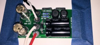
PCBoards arrived from the fab yesterday, and after an antivirus scrubbing and subsequent low temperature bake, I assembled one today. See Figures 1 and 2 below.
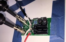
Unfortunately, the probes that came with my scope did not include probe-to-BNC adapters. So I bought two new "200MHz" probes from Amazon, for USD 23.00. These probes DO come with probe-to-BNC adapters: (Amazon link). You can see the probes and their adapters in Figure 3 below. Notice that the ground of the probe and the ground plane of the PCB are in intimate and low-inductance contact, thanks to the body of the BNC connector.
For this test I used a wall wart from Mean Well, part number GST25U28-P1J. It's a 28 volts DC output supply, rated for 25 watts (0.893 amps). I connected my DC electronic load and set it for 0.80 amps, so I was pushing the SMPS pretty hard but still within its rated specs.
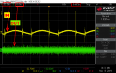
Figure 4 shows the scope waveforms I obtained with the Figure 3 setup. On top in yellow is the filter "input" which is just the output of the wall wart. On the bottom in green is the filter "output" which delivers current to the load. Figures 5 and 6 show the same setup at finer horizontal resolution.
The peak-to-peak noise at the (yellow) input is 5.0 vertical divisions, which equals 250 millivolts. Peak-to-peak noise at the (green) output is 1.0 vertical division, which equals 10 millivolts. So the filter output has less noise than the filter input, by a factor of (250 / 10) = 25X. I am pleased with this result.
No doubt some readers will remark "Hey! Why don't you lay out one more test jig which connects two PO89ZB's in series cascade, with equally good high speed probing and equally good low inductance grounding? That would be a lot of fun!". My answer is: please feel free to do this yourself and enjoy the work + the results. I won't be doing this myself.
_
PCBoards arrived from the fab yesterday, and after an antivirus scrubbing and subsequent low temperature bake, I assembled one today. See Figures 1 and 2 below.
Unfortunately, the probes that came with my scope did not include probe-to-BNC adapters. So I bought two new "200MHz" probes from Amazon, for USD 23.00. These probes DO come with probe-to-BNC adapters: (Amazon link). You can see the probes and their adapters in Figure 3 below. Notice that the ground of the probe and the ground plane of the PCB are in intimate and low-inductance contact, thanks to the body of the BNC connector.
For this test I used a wall wart from Mean Well, part number GST25U28-P1J. It's a 28 volts DC output supply, rated for 25 watts (0.893 amps). I connected my DC electronic load and set it for 0.80 amps, so I was pushing the SMPS pretty hard but still within its rated specs.
Figure 4 shows the scope waveforms I obtained with the Figure 3 setup. On top in yellow is the filter "input" which is just the output of the wall wart. On the bottom in green is the filter "output" which delivers current to the load. Figures 5 and 6 show the same setup at finer horizontal resolution.
The peak-to-peak noise at the (yellow) input is 5.0 vertical divisions, which equals 250 millivolts. Peak-to-peak noise at the (green) output is 1.0 vertical division, which equals 10 millivolts. So the filter output has less noise than the filter input, by a factor of (250 / 10) = 25X. I am pleased with this result.
No doubt some readers will remark "Hey! Why don't you lay out one more test jig which connects two PO89ZB's in series cascade, with equally good high speed probing and equally good low inductance grounding? That would be a lot of fun!". My answer is: please feel free to do this yourself and enjoy the work + the results. I won't be doing this myself.
_
Attachments
Last week I edited the PO89ZB printed circuit layout, and added a couple of BNC jacks for high speed signal probing, including ultra low inductance ground connections. I followed the recommendations in Johnson & Graham's textbook (link), as best as I could on a two layer board....
Yeah, to get my copper clad 3 stage 5A filter breadboard scope measurements, I had solder on some BNC connectors and used those BNC/probe adapters. The Siglent scope came with those adapters. The probe adapters and BNCs are great for dealing with high frequency noise.
Very nice... and very instructive (again).
Mark, if I am not mistaken, said SMPS has 150mV peak to peak advertised max ripple & noise, but here, in real life, it in fact exceeds that, making your excellent filter even more valuable.
I have to say I tended so far to trust the values on the Meanwell specsheets and was always surprised by the great sonic impact your filters could have on various devices despite looking sometimes "probably negligeable on the paper"... perhaps one part of the explanation is that these wallwart SMPS are worst than expected in real life and need even more filter curing.
Thanks again for sharing all this and stay safe
Claude (going into the 3rd lockdown, well, might give us more time for measurments...)
- Home
- Source & Line
- Analog Line Level
- PO89ZB , an inline DC filter for SMPS wall warts . Preamps, HPA, Korg NuTube, etc