A little less than a year after I relased V2 of my attenuator, V3 is finally done and tested and it works absolutely perfect.
Description :
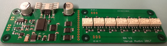
Fully HW-based pop and click free relay attenuator.
All done with some clever use of digital logic and accurate timing.
127 x 0.6dB steps for an attenuation range of 0 to -76.2dB.
High quality Omron G6K relays, high quality low noise, low distortion 0.1% Panasonic 1206 ERA Thin Film resistors.
Perfect channel balance, from max to min attenuation.
The attenuator needs a 10K termination resistor to maintain a 10K total attenuator impedance.
Use a 100K Linear potentiometer to adjust the ADC input voltage.
150mm x 40mm 4 Layer ENIG PCB.
Changes from V2 :
1. A few Bugfixes : No board level modifications are needed on V3. Q1 is now a Mosfet instead of a BJT.
2. Improvements : The board is now uisng an external on-board clock source instead of the built in oscillator in ADC0804. The built in oscillator circuit just isn't good enough.
3. Simplification : The detent function that stabilizes the circuit by using the LSB has been made simpler but it still works as intended.
4. Expandability : Stackable expander board(s), there is now an extra output header that can be used to stack additional boards on top of the main attenuator board.
Build tips :
The supply voltage to the board should be between 14-18VDC for the attenuator board alone and 1 expander board. This is enough to control a balanced/differential signal.
If using 2 or 3 expander board I would personally keep the supply voltage to 14-15VDC to keep the dissipation in U12 to a reasonable level(below 800-900mW.
When ordering componenets the majority of them can be supplied from Mouser but 4 of the Thin Film resistors should be oredered from Digikey. However, everyone is free to use whatever resistors they like, as long as they fit on a 1206 footprint.")
It is not needed to order the 14 Pin Male Header if you are only using the attenuator for SE stereo signals.
2. Selecting Potentiometer : Almost any 100K Linear potentiometer will work, but I personally use this one from Bourns :
Mouser : 53RAA-R25-A20L Bourns | Mouser Denmark
Digikey : 53RAA-R25-A20L Bourns Inc. | Potentiometers, Variable Resistors | DigiKey
Ordering: The price is 20$ per PCB and I only have a small batch available
Shipping is 5$ anywhere in the world. Additional shipping charges may apply if the number of PCB's ordered exceed the weight limit for 5$ shipping.
Send me an E-mail with your DiyA username, real name, adress and E-mail adress and I will send you a PayPal request. Since this is a hobby it might take me a day or two to reply and a few more days to ship. I hope people can live with that.
EDIT : The component placement drawing is not 100% correct, the CON1/CON2 connectors are actually 5mm more to the left than what is shown.
Description :
Fully HW-based pop and click free relay attenuator.
All done with some clever use of digital logic and accurate timing.
127 x 0.6dB steps for an attenuation range of 0 to -76.2dB.
High quality Omron G6K relays, high quality low noise, low distortion 0.1% Panasonic 1206 ERA Thin Film resistors.
Perfect channel balance, from max to min attenuation.
The attenuator needs a 10K termination resistor to maintain a 10K total attenuator impedance.
Use a 100K Linear potentiometer to adjust the ADC input voltage.
150mm x 40mm 4 Layer ENIG PCB.
Changes from V2 :
1. A few Bugfixes : No board level modifications are needed on V3. Q1 is now a Mosfet instead of a BJT.
2. Improvements : The board is now uisng an external on-board clock source instead of the built in oscillator in ADC0804. The built in oscillator circuit just isn't good enough.
3. Simplification : The detent function that stabilizes the circuit by using the LSB has been made simpler but it still works as intended.
4. Expandability : Stackable expander board(s), there is now an extra output header that can be used to stack additional boards on top of the main attenuator board.
Build tips :
The supply voltage to the board should be between 14-18VDC for the attenuator board alone and 1 expander board. This is enough to control a balanced/differential signal.
If using 2 or 3 expander board I would personally keep the supply voltage to 14-15VDC to keep the dissipation in U12 to a reasonable level(below 800-900mW.
When ordering componenets the majority of them can be supplied from Mouser but 4 of the Thin Film resistors should be oredered from Digikey. However, everyone is free to use whatever resistors they like, as long as they fit on a 1206 footprint.
It is not needed to order the 14 Pin Male Header if you are only using the attenuator for SE stereo signals.
2. Selecting Potentiometer : Almost any 100K Linear potentiometer will work, but I personally use this one from Bourns :
Mouser : 53RAA-R25-A20L Bourns | Mouser Denmark
Digikey : 53RAA-R25-A20L Bourns Inc. | Potentiometers, Variable Resistors | DigiKey
Ordering: The price is 20$ per PCB and I only have a small batch available
Shipping is 5$ anywhere in the world. Additional shipping charges may apply if the number of PCB's ordered exceed the weight limit for 5$ shipping.
Send me an E-mail with your DiyA username, real name, adress and E-mail adress and I will send you a PayPal request. Since this is a hobby it might take me a day or two to reply and a few more days to ship. I hope people can live with that.
EDIT : The component placement drawing is not 100% correct, the CON1/CON2 connectors are actually 5mm more to the left than what is shown.
Attachments
-
Relay Attenuator V3_Schematic_Digital Logic.pdf30.3 KB · Views: 1,187
-
Relay Attenuator V3_Schematic_Supply-Relays.pdf29 KB · Views: 944
-
Relay Attenuator V3_Component Placement.pdf36.1 KB · Views: 629
-
Relay Attenuator V3_BOM_Simple.pdf31.6 KB · Views: 475
-
Relay Attenuator V3_BOM_Mouser_Partial.txt759 bytes · Views: 333
-
Relay Attenuator V3_BOM_Digikey_Partial.txt65 bytes · Views: 294
-
 Complete.png840.9 KB · Views: 2,439
Last edited:
Excellent!
Do you have expander boards available?
I am sorry to inform you that I have no expander boards.
They are not a high priority since I have a feeling that there is limited interest in those.
But I will se what happens, if it turns out that there is a decent interest in them I might make them available anyway.
Very nice project made with Eagle. Congratulations!
I had previously thought of a potentiometer with ADC. How do you prevent the 1-bit jitter?
U6/R32/R33 prevents 1-bit jitter.
Last edited:
If we need to make the expander boards ourselves, will you make the Gerbers/BOMs/other documents freely available?
Same question.
With regards to the expander boards, if there is enough interest, enough interest being a minimum of 5 pcs of them, I will make small a batch.
The size is 86mm x 40 mm and the price would be 15$, not that much cheaper than the larger main attenuator board but that is what you get with smaller batches.
The size is 86mm x 40 mm and the price would be 15$, not that much cheaper than the larger main attenuator board but that is what you get with smaller batches.
Last edited:
I would be interested in a main board and two expander boards.With regards to the expander boards, if there is enough interest, enough interest being a minimum of 5 pcs of them, I will make small a batch.
The size is 88mm x 40 mm and the price would be 15$, not that much cheaper than the larger main attenuator board but that is what you get with smaller batches.
I'm just thinking about the V3. The V3 uses 128 steps. Wouldn't 64 steps be enough? 128 has twice as many relay clicks. Does anyone have experience with 64 relay volume controls.
You could just leave out K1/R15/R16 and replace R1/R2 with 0 Ohm resistors(or wirelinks) and then recalculate the step size so you would get 64 steps with each step being 1dB. Then you would have -63dB attenuation(Step 64 is 0dB attenuation so maximum attenuation would be -63dB).
Thanks for the advise! I meant, is it possible that there is too much audible jump with 64?
Another question: You said that the osc.-frequency was to bad in v2 compared to v3 now. Why? Does the accuracy matter so much?
It depends. If you increase the step size you will get bigger jumps between volume steps. However, around 1dB should be good enough for most people, many commercial attenuators use 1dB step size so I think it would be good enough.
On V1 and V2 I used the built in RC oscillator function of the ADC0804 and whilte the frequency is fairly stable, the initial frequency can vary a lot with the voltage threshold variations of the Schmitt Trigger built into the ADC0804.
Using an external oscillator is just much more predictable and you will get the same frequency everytime across several boards.
I just placed an order for a small batch of expander PCBs.
They should arrive within the next 10 days.
See attached documents for info regarding the expander boards.
Build tips :
If you want to use an expander board you need CON5(14 Pin Male Header) on the main attenuator board and on the expander board you need CON4(14 Pin Female Header). You do not have to order CON3, that is only if you want to stack more than 1 expander board on top of the main attenuator board. CON4 should be placed on the bottom of the expander PCB in the location of CON3 for easy mating with the main attenuator board. But it should be easy to figure out, CON4 can only be placed one way if you want to stack it with the main attenuator board.
Something else to take into account is that the 3 Pin molex headers used for audio In/GND/Out on both the main attenuator board and the expander board can not be used on the main attenuator board when stacking an expander board on top of it. There you would either have to order some right angle molex connectors or just solder the wires to the pads instead.
I also recommend using 10mm standoffs between the main attenuator board and the expander board, then everything should fit perfectly.
EDIT : The component placement drawing is not 100% correct, the CON1/CON2 connectors are actually 5mm more to the left than what is shown.
Attachments
Last edited:
Brilliant! I've PM'ed you with order details for the main board and an expander board. Meanwhile I'm trying to get the BOM together. Is it acceptable to substitute a 2N7200BK-215 for the 2N7200P-215? The 2 MOSFETs have very similar characteristics but the 2N7200P seems out of stock at the usual places until July.
Brilliant! I've PM'ed you with order details for the main board and an expander board. Meanwhile I'm trying to get the BOM together. Is it acceptable to substitute a 2N7200BK-215 for the 2N7200P-215? The 2 MOSFETs have very similar characteristics but the 2N7200P seems out of stock at the usual places until July.
That is acceptable. Q1 is not that critical, any 2N7002 in a SOT-23 package would be suitable.
The attenuator needs a 10K termination resistor to maintain a 10K total attenuator impedance.
Would like to know that if use this to replace an ALPS RK27 50K pot, do I need to change anything?
Would like to know that if use this to replace an ALPS RK27 50K pot, do I need to change anything?
I do not know, do you have a schematic I can see? Without a schematic it is hard for me too know how much and what you might have to change.
But in general, from the output on this relay attenuator you need a resistance of 10K to GND. Otherwise the step size, depending on volume setting, will vary too much and not be exactly 0.6dB as intended.
- Home
- Source & Line
- Analog Line Level
- Pop/click free HW-based relay attenuator V3