If the desired approach is less boxes then why add so many boxes in 1 box?")
The only box in a box is for the dam1941 and rpi ian canada stuff, an attempt for some shielding.
Regards,
John
Project update, pics and a few questions..
Evening all..
Have been slowly making progress on my DCG3 albeit pretty slowly! Today I was able to perform the electrical test steps in the build guide and I have a few questions about numbers I'm seeing.
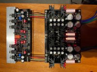
All parts are from Tea-Bag and pretty vanilla build so far. DCSTB setup for dual supplies via recommended Antec AS-0518's. Rail voltages from power supply are: 17.07/-17.06 and 17.06/-16.95.
Power up of DCG3 board went pretty well.. I'm using 10R at R10 for bias at 120 and they measured very accurately. After letting things warm up (and they did) I shorted the inputs to set the DC offset. Both sides started at 260ish millivolts and I was somewhat surprised by how many turns of V1 it required to get them in the ballpark. The guide alludes to the offset numbers wandering a little bit.. I'm wondering how much is 'too much'? I've got them both dialed in to a zero 'ish' baseline, but they are both oscillating at a max of up to +/- 20mv? Is this a 'get them in the ballpark and move on' thing or do I need to continue trying to iron out some of this oscillation?
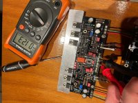
Next question is temps of M1/2/3 on both sides.. I'm surprised how warm the heat sink is getting.. Not really able to measure the alum bar very precisely with my IR temp gun, but I'm I'm getting the following temps at each mosfet.
Left side: M1 135f/57c M2 98f/36c M3 146F 63C
Right side: M1 135f/57c M2 139f/59c M3 92f/33C
Any concern with these temps? Data sheets show both good to 150c..
I was very careful mounting the mosfets on the heat sink and I'm 100 percent certain that there is no electrical continuity between mosfets and sink..
Thanks for taking a look, can't wait to get this thing paired up with my Aleph J and Hersey speakers!
Cheers all!
John
Evening all..
Have been slowly making progress on my DCG3 albeit pretty slowly! Today I was able to perform the electrical test steps in the build guide and I have a few questions about numbers I'm seeing.
All parts are from Tea-Bag and pretty vanilla build so far. DCSTB setup for dual supplies via recommended Antec AS-0518's. Rail voltages from power supply are: 17.07/-17.06 and 17.06/-16.95.
Power up of DCG3 board went pretty well.. I'm using 10R at R10 for bias at 120 and they measured very accurately. After letting things warm up (and they did) I shorted the inputs to set the DC offset. Both sides started at 260ish millivolts and I was somewhat surprised by how many turns of V1 it required to get them in the ballpark. The guide alludes to the offset numbers wandering a little bit.. I'm wondering how much is 'too much'? I've got them both dialed in to a zero 'ish' baseline, but they are both oscillating at a max of up to +/- 20mv? Is this a 'get them in the ballpark and move on' thing or do I need to continue trying to iron out some of this oscillation?
Next question is temps of M1/2/3 on both sides.. I'm surprised how warm the heat sink is getting.. Not really able to measure the alum bar very precisely with my IR temp gun, but I'm I'm getting the following temps at each mosfet.
Left side: M1 135f/57c M2 98f/36c M3 146F 63C
Right side: M1 135f/57c M2 139f/59c M3 92f/33C
Any concern with these temps? Data sheets show both good to 150c..
I was very careful mounting the mosfets on the heat sink and I'm 100 percent certain that there is no electrical continuity between mosfets and sink..
Thanks for taking a look, can't wait to get this thing paired up with my Aleph J and Hersey speakers!
Cheers all!
John
Attachments
Last edited:
You shouldn't be alarmed by how many turns it took to zero the offset, as long as you can zero it. Some drift is expected with the op-amp out. What does the offset do once you put the op-amp in its socket?
I'm a little surprised by the temperature readings. Not the absolute values, but the differences. M1 and M2 split the positive rail voltage, whereas M3 takes the full voltage -- so I'd expect M3 to run hotter by a significant margin on both channels.
The temperatures are not dangerous for the devices, but you have effectively no heatsinking there. You should try bolting the output transistors to something with a lot more surface area.
Do you have an oscilloscope? As a matter of course, I would want to check any feedback amplifier for ultrasonic oscillation, which could cause strange problems with heating and offset. How does it sound on headphones? In my experience, if there are no hums/buzzes/clicks when you plug the headphones in and out, and if the music sounds good, then you're probably doing fine.
As always, your mileage may vary.
You shouldn't be alarmed by how many turns it took to zero the offset, as long as you can zero it. Some drift is expected with the op-amp out. What does the offset do once you put the op-amp in its socket?
I'm a little surprised by the temperature readings. Not the absolute values, but the differences. M1 and M2 split the positive rail voltage, whereas M3 takes the full voltage -- so I'd expect M3 to run hotter by a significant margin on both channels.
The temperatures are not dangerous for the devices, but you have effectively no heatsinking there. You should try bolting the output transistors to something with a lot more surface area.
Do you have an oscilloscope? As a matter of course, I would want to check any feedback amplifier for ultrasonic oscillation, which could cause strange problems with heating and offset. How does it sound on headphones? In my experience, if there are no hums/buzzes/clicks when you plug the headphones in and out, and if the music sounds good, then you're probably doing fine.
As always, your mileage may vary.
hpasternack,
Thank you for responding.. I should have prefaced my post by also saying "I largely have no idea what I"m doing.." lol.. Anyway, I let it cool down and just powered it back up, I"ll take temps again..
Regarding the oscillation of offset, I didn't install the opamp at all yet because I was concerned something was afoul and didn't want to risk cooking the opamp. If +-20ma of oscillation isn't alarming, I can give it a go and report back! I don't yet have an oscilloscope and haven't done any wiring yet to be able to see how anything sounds via phones..
The purpose of the op-amp is to sense and cancel the DC offset at the output. It's unlikely that you'll blow the op-amp if you put it in the socket. If you're measuring about 1.2V across both R10s then that means the output stage current source is working properly and in all likelihood everything else is too. Once you put in the op-amp, the offset should drop to maybe 1mV or so. It will still drift, but should stay much closer to zero, which tells you the op-amp (DC servo) is working properly.
Another thing you can check once the op-amp is installed is what the voltage is on the gate of J2. It should be very close to zero also.
I wouldn't fret too much. It sounds like everything is in order.
-Henry
Another thing you can check once the op-amp is installed is what the voltage is on the gate of J2. It should be very close to zero also.
I wouldn't fret too much. It sounds like everything is in order.
-Henry
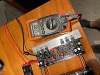
On further thought, if you want to do some more checking, try taking the drain, gate, and source voltages for each of M1, M2, and M3 on both channels and post the values. That would be definitive, I think.
-Henry
Henry.. Thank you for the suggestions.. Do you mind briefly explaining how to take those measurements? Embarrassingly, I'm not familiar enough to grab those values..
-john
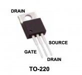
Sure. I've attached a diagram of the pin assignments of your output transistors. The IRF9610 and DN2540 are both the same this way. So, connect the negative lead of your meter to ground, set the meter to the Volts scale, and carefully get a reading on each pin of all six output devices. Make a little table and post the values and I can tell you at a glance if everything is biased up correctly.
Again, I'm just suggesting this as an exercise. I don't see any signs of trouble.
Edit: You can also check pin 8 of the IC socket (+17V) and pin 4 (-17V). If that checks out -- and there is no reason it shouldn't -- then you are basically good to plug in the AD823.
-Henry
Again, I'm just suggesting this as an exercise. I don't see any signs of trouble.
Edit: You can also check pin 8 of the IC socket (+17V) and pin 4 (-17V). If that checks out -- and there is no reason it shouldn't -- then you are basically good to plug in the AD823.
-Henry
Attachments
Last edited:
@SkyPirate
Regarding your first adjustment questions, the initial large DC offset is caused by the factory mid setting of the 20R trimmers because the needed value is low, only about four Ohms. Hence the many turns taken to home in.
Not having full chassis floor mount or sink yet, just the Alu bar, won't damage the Mosfets but its not yet their final temperature condition. I recommend you do a final readjust after fully installed. A grounded chassis will provide better thermal and interference stability.
Your rail voltages and bias indications are very textbook, there is very good tolerance in your active parts matching it seems.
See the DC offset without shorted input also and then try with the Op-Amp. Your build seems like behaving very normally up to now.
Not really able to measure the alum bar very precisely with my IR temp gun, but I'm I'm getting the following temps at each mosfet.
Left side: M1 135f/57c M2 98f/36c M3 146F 63C
Right side: M1 135f/57c M2 139f/59c M3 92f/33C
Check the the temps again with a contact temp probe if you got one. Especially the highlighted ones. IR gun can be reflecting oddly on the tabs, screws, and bar. All silver.
Sure. I've attached a diagram of the pin assignments of your output transistors. The IRF9610 and DN2540 are both the same this way. So, connect the negative lead of your meter to ground, set the meter to the Volts scale, and carefully get a reading on each pin of all six output devices. Make a little table and post the values and I can tell you at a glance if everything is biased up correctly.
Again, I'm just suggesting this as an exercise. I don't see any signs of trouble.
Edit: You can also check pin 8 of the IC socket (+17V) and pin 4 (-17V). If that checks out -- and there is no reason it shouldn't -- then you are basically good to plug in the AD823.
-Henry
Perfect!
Ok.. Interesting exercise.. All numbers were taken still with opamp out.. Also, the temps all stabilized a bit between mosfets.. M3's now at 133ish.. M1/2 now high 120's.. much closer than earlier..
L Side (Gate/Source/Drain)
M3 -17.4/-36/-15.8
M1 12.82/8.5/17.6
M2 4.25/-24/8.49
R Side (Gate/Source/Drain)
M2 4.23/-9/8.46
M1 12.78/8.45/17.02
M3 -16.92/-12/-15.7
Seemed like some of them locked in very solidly, but some (Many of the source pins) were varying a good bit.. so I had to 'average' what was showing.. All gibberish to me!
Check the the temps again with a contact temp probe if you got one. Especially the highlighted ones. IR gun can be reflecting oddly on the tabs, screws, and bar. All silver.
Hi Salas.. Thank you! For some reason the temps seem to be much more consistent now.. I don't have a contact thermometer, but when I aim the IR at the center point of the black plastic housing I'm getting M3's 137 and 132.. M1's and M2's all between 125 and 132F.
@SkyPirate
Regarding your first adjustment questions, the initial large DC offset is caused by the factory mid setting of the 20R trimmers because the needed value is low, only about four Ohms. Hence the many turns taken to home in.
Not having full chassis floor mount or sink yet, just the Alu bar, won't damage the Mosfets but its not yet their final temperature condition. I recommend you do a final readjust after fully installed. A grounded chassis will provide better thermal and interference stability.
Your rail voltages and bias indications are very textbook, there is very good tolerance in your active parts matching it seems.
See the DC offset without shorted input also and then try with the Op-Amp. Your build seems like behaving very normally up to now.
Will do.. Thanks for the confirmation! Appreciate you still being on here after YEARS of offering outstanding tech support..
-j

A simple check is read Vgs (DC voltage between pins 1 & 3) for each Mosfet. Comparing Vgs of M1 M2 M3 between channels tells if they are biased about the same in their respective positions. There are Vgs tolerances in M1 M2 Mosfets but they should be in the same ball park. M3 Mosfets already look matched because reading same 1.2V over 10R i.e. same 120mA output stage bias.
Sorry, I deleted my earlier post. I'm a little tired and have been slumming at home all day. My brain isn't firing on all two cylinders. Let me try again.
Some of your measurements look good. I believe you transposed the drain and source numbers. Other measurements look wrong, and a couple seem impossible.
I suspect the problem is measurement error, not the circuit. If there were something seriously wrong, you would know because there would be heat, and possibly smoke, and probably a severe DC offset on the output.
Because you don't have any of those bad things, I second Salas' assessment that everything is operating properly.
Since this circuit has a lot of gain internally, it benefits from being installed in a properly-shielded enclosure. I've made three of these and I think you should at least put it on a metal plate, with a single connection between the signal board ground and the plate.
Mostly, I encourage you to have confidence and not to worry.
-Henry
Last edited:
Sorry, I deleted my earlier post. I'm a little tired and have been slumming at home all day. My brain isn't firing on all two cylinders. Let me try again.
Some of your measurements look good. I believe you transposed the drain and source numbers. Other measurements look wrong, and a couple seem impossible.
I suspect the problem is measurement error, not the circuit. If there were something seriously wrong, you would know because there would be heat, and possibly smoke, and probably a severe DC offset on the output.
Because you don't have any of those bad things, I second Salas' assessment that everything is operating properly.
Because this circuit has a lot of gain internally, it benefits from being installed in a properly-shield enclosure. I've made three of these and I think you should at least put it on a metal plate, with a single connection between the signal board ground and the plate.
Mostly, I encourage you to have confidence and not to worry.
-Henry
Henry!
Me too.. too many 330am wake ups in the last week for me.. You're right.. I read the pins incorrectly and transposed the drain and source.. I'm so sorry.. I'm certain that I measured something incorrectly, and it's possible that my meter may have been telling me "mV" and I wrote down V.. The delta in voltage between pins 1 and 3 on respective sides is all very close (See Salas suggestion above), so I'm assuming measurement error of some kind on my behalf..
Thanks for the reminder to be confident and press on.. This is only my third DIY project and so far, barring one misplaced resistor everything has worked wonderfully.. Thank you for jumping in to offer your expertise and sorry if I caused you to burn brain cells unnecessarily!
-j
Last edited:
It's all good, not to worry. And thank you for bearing with me.
Here are your measurements with the column labels fixed and suspect measurements changed to mV:
Since the drains of M2 and M3 are connected together and to the output, the readings should be the same and close to zero. I agree, your meter probably auto-ranged into the mV scale, and that explains the anomalous readings and the fact they weren't stable.
I've been through a few batches of DN2540s. Within a batch they are always close, but Vgs for the batches has varied from about 1.0 to 1.5V. Your 1.2V measurement is good.
The IRF9610s should bias up around 4V, so again your readings are spot-on as expected. The difference between 4.25V and 4.23V is insignificant.
I'm going to go for a walk -- it might clear my brain fog. Perhaps you will put in that op-amp and post your results before I get back?
-Henry
Here are your measurements with the column labels fixed and suspect measurements changed to mV:
L Side (Gate/Drain/Source)
M3 -17.4/-36mV/-15.8
M1 12.82/8.5/17.6
M2 4.25/-24mV/8.49
R Side (Gate/Drain/Source)
M2 4.23/-9mV/8.46
M1 12.78/8.45/17.02
M3 -16.92/-12mV/-15.7
Since the drains of M2 and M3 are connected together and to the output, the readings should be the same and close to zero. I agree, your meter probably auto-ranged into the mV scale, and that explains the anomalous readings and the fact they weren't stable.
I've been through a few batches of DN2540s. Within a batch they are always close, but Vgs for the batches has varied from about 1.0 to 1.5V. Your 1.2V measurement is good.
The IRF9610s should bias up around 4V, so again your readings are spot-on as expected. The difference between 4.25V and 4.23V is insignificant.
I'm going to go for a walk -- it might clear my brain fog. Perhaps you will put in that op-amp and post your results before I get back?
-Henry
Those numbers are perfect. Salas will reply in a moment and say the same...

It's all good, not to worry. And thank you for bearing with me.
Here are your measurements with the column labels fixed and suspect measurements changed to mV:
Since the drains of M2 and M3 are connected together and to the output, the readings should be the same and close to zero. I agree, your meter probably auto-ranged into the mV scale, and that explains the anomalous readings and the fact they weren't stable.
I've been through a few batches of DN2540s. Within a batch they are always close, but Vgs for the batches has varied from about 1.0 to 1.5V. Your 1.2V measurement is good.
The IRF9610s should bias up around 4V, so again your readings are spot-on as expected. The difference between 4.25V and 4.23V is insignificant.
I'm going to go for a walk -- it might clear my brain fog. Perhaps you will put in that op-amp and post your results before I get back?
-Henry
Henry,
Thank you for correcting all of my bafoonery.. lol.. Ok.. Opamp installed.. Input pins shorted.. I'm getting 0 +/-2.5mV on the left side, and 0 +/- 1.5mV on the right side.. I didn't realize that the purpose of the opamp was to reduce the variance of DC Offset.. I could probably tweak the left side a tad and get that number closer..
Thanks for hanging in there with ME! I need to finalize my decision on the chassis and pull the trigger on that.. Rest of the parts are here minus the pot extension shaft and bracket.. And your assesment of "you may be overthinking it".. lol.. #Truth
- Home
- Source & Line
- Analog Line Level
- Salas DCG3 preamp (line & headphone)