 to you too!
He probably meant preferring DAC3 through DCG3 although that Benchmark DAC has been designed to can fully drive a power amp straight, and he had tried both ways. At least as I understood.
Its own brand mating amp is AHB2 by the way. A particularly insensitive XLR input model to enhance SNR. Both are top technical performers. SINAD metric champions so to say.
Exactly that! thanks Nick!
")
Dear Mr Salas,
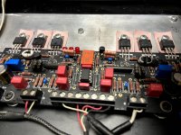
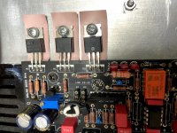
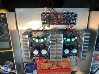
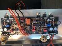
here I am after making some changes to your fantastic preamp.
First I replaced, as I announced, the potentiometer, from a blue alps to the TKD and the difference was abysmal, I don't know the terms to describe the change, I can only tell you that the music seemed to me like it was taking life.
Then I finished the Nelson Pass project the First Watt F6 and the match is a winner, I have ELAC DEBUT 2.0 F6.2 and they never sounded like this. But the pre gain was not enough for this amplifier, so I replaced the R6 with about 1.6K (two 3.3k in parallel) and I got an excellent result, a little more power, just right for my listening room.
At this point I was in the mood for change and I replaced Q1 and Q2 with matched BC327-40, obtaining a sound that seems more airy to me.
Finally I bought a second headset, I had a Focal Spirit but it was too uncomfortable, I could not keep it more than half an hour, and I bought a Beyerdynamic DT 770 PRO 250 Ohm and I had to change R10 to R7.5 and now the system is a bomb, I'm very happy.
A couple of questions if I can:
If I want to get a little more power out of the F6, do you think I can increase the gain further by changing R6 or do I risk clipping?
The input selector, feeds it from the power supply output, i.e. between a positive branch and GND. Is this correct or is it better to take one of the transformer outputs and power the I-Select directly before the rectifier?
I attach some photos of the changes, thank you very much to you and to all the enthusiasts of this forum!
Attachments
Hi, this preamp has no input buffering, on purpose to keep number of stages minimal, so the pot's value and quality are integral parts of its bandwidth spec and sound. Thus you did well to splash out on a better pot.
That selector board was originally designed for general use, even stand alone, that is why it can be powered from an independent transformer or secondary, thus also having a fully fledged PSU of its own. When having a proper DC source for feeding it though, just prefer it. Phasing of transformer wires can create problems if tapping from a shared secondary. A voltage difference between DCSTB's gnd and selector's PSU gnd maybe arising, that's a no go sign.
BC327-40 is my personal preference here too. It works more towards a kinder sound I think. BC560C can lend starker contrast synergistic with softer speaker and room interface or with rounder headphone listening tastes. Just shorten their legs to fit more rigidly in the sockets now that you know they are keepers for you.
About increasing the preamp gain dose for your F6 once again, you are the one to judge how much is too much because its a system gain and speakers sensitivity, also room and listener, related thing. But it may prove too much for headphones listening. Keep in mind this pot opens up high volume later than most. It certainly brings no electrical problems to DCG3 itself upping the gain a bit more and you can always revert.
You are welcome and enjoy!
@ Thejekocomputer,
Maybe you can have a look at Salas's post #4839. At first the selector was powered by one of the transformers: noise and ended by cutting the selector diodes.
Now the selector is powered by its DCin through one of the DCSTB outputs: fine.
Edit: was typing as Salas was replying.
Maybe you can have a look at Salas's post #4839. At first the selector was powered by one of the transformers: noise and ended by cutting the selector diodes.
Now the selector is powered by its DCin through one of the DCSTB outputs: fine.
Edit: was typing as Salas was replying.
Some did happily tap on shared AC but result depends on secondary phasing and general grounding method. My advice is avoid since compatible DC sources are in the same area. Fundamentally its not sound practice to share a secondary between different bridge rectifiers. Other guys with some additional small dedicated transformer or a dedicated secondary from a main transformer to the selector board never had problems connecting grounds. But its superfluous.
Building of boards and assembly onto chassis with 3 input selector board and 20k motorised potentiometer with remote control board is complete. These additional boards are from a Silicon Chip preamp of 2011 modified to remove signal electronics.
The chassis is now being run to test everything. It has been going now for 6 hours, playing happily. First impression is the absolute clarity of the sound with total absence of any background hiss or noise, simply stunning.
The power supplies read: right channel V+ 16.97 V- 17.00, left channel V+ 17.18 V- 17.23
The gain is set at 3. Channel offsets at their outputs are <1 mV.
When the enclosure is completed I will post photos.
Salas this is an absolutely stunning piece of design, but you knew that already! Tea-Bag's kits went together very easily and were really straightforward to get right. As usual, other people's experiences helped enormously in keeping me on the right track and your advice to us all is very reassuring and encouraging. Thank you both for your endeavours.
Graeme
Hmmmm since I want to build a balanced Version of the dcg3 I am thinking about placing the stuff in two 2HE cases..
What would be better, the psus in one case (4 of them and 4 toroids) and the dcg boards, input selector and volume in the second or psus and dcg in one case and the Other stuff in the second?
What would be better, the psus in one case (4 of them and 4 toroids) and the dcg boards, input selector and volume in the second or psus and dcg in one case and the Other stuff in the second?
If it has to be two chassis I would put two 100VA transformers in one box along with high quality rectifiers and big reservoir capacitors.
I would skip the rectifiers on the DCSTBs and keep the local 2200uF caps as decouplers. Converting them to DC input. Still keeping those two DCSTB bipolar sections near the DCG3s with short rail cables in the other chassis. Shared PSU between balanced signal phase channels is seen common mode and tends to be better rejected. See posts #4807-4810.
I would skip the rectifiers on the DCSTBs and keep the local 2200uF caps as decouplers. Converting them to DC input. Still keeping those two DCSTB bipolar sections near the DCG3s with short rail cables in the other chassis. Shared PSU between balanced signal phase channels is seen common mode and tends to be better rejected. See posts #4807-4810.
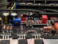
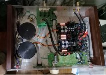
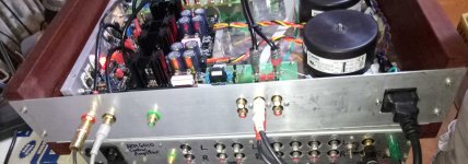
Hi All. This is my first attempt at building a SS peramp. I've followed the instructions but probably did something wrong. I'm getting very nasty hum.
The UBIBs are set to 16V & -16V on both channels. DC offset is less than 1 mV on one channel and ~3mV on the other channel. Voltage on R10 is ~1V on both channels. I did not put a potentiometer on the input and also did not solder RZJ as I dont use the headphone output. Maybe you can give advice how to debug this? I have access to scope and lab power supplies if needed.
The UBIBs are set to 16V & -16V on both channels. DC offset is less than 1 mV on one channel and ~3mV on the other channel. Voltage on R10 is ~1V on both channels. I did not put a potentiometer on the input and also did not solder RZJ as I dont use the headphone output. Maybe you can give advice how to debug this? I have access to scope and lab power supplies if needed.
Attachments
Hi
Difficult to guess as it looks like in midway build phase still. For example no coaxial cables at the outputs, no chassis ground as far I can see, also I don't know what the brown board does or what are or where are the transformers.
Anyway, firstly I hope there is no shared secondary between some Ubib sections. Each AC input needs its own dedicated secondary winding wires pair. If not, there could be problems due to that.
Secondly, and if hum is not due to some systemic ground loop, try 4.7k resistors between each input RCA hot pin and board's input so to mimic a pot's output impedance. It shouldn't normally react even as it is now, but maybe it doesn't like something in your test source or cabling right now.
For RZJ you can simply put wire links so to have the headphones output ready for any possibility in the future. 1V on R10 tells you the output stage bias when divided by the R10 value you use. If 10Ω its 100mA for instance.
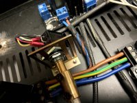
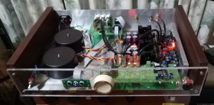
As promised in #4849 I attach photos of the completed preamp (without lid which is still under construction).
Have had a chance to listen on my Sennheiser HD 595 headphones and I repeat my earlier comment about the clarity of sound and freedom from extraneous hum and noise for this superb design.
Love this piece of gear.
Graeme
Have had a chance to listen on my Sennheiser HD 595 headphones and I repeat my earlier comment about the clarity of sound and freedom from extraneous hum and noise for this superb design.
Love this piece of gear.
Graeme
Attachments
- Home
- Source & Line
- Analog Line Level
- Salas DCG3 preamp (line & headphone)