Measure mv drop across one of your 0.47R per side then divide by 0.47. That number will be mA through the leds each one side is connected. The real life color is red with little orange tone. Don't trust the photos exactly because the gadgets we shoot with adjust the white balance whatever. Those leds we connect in series so what current one has all other have the same.
Measure mv drop across one of your 0.47R per side then divide by 0.47. That number will be mA through the leds each one side is connected. The real life color is red with little orange tone. Don't trust the photos exactly because the gadgets we shoot with adjust the white balance whatever. Those leds we connect in series so what current one has all other have the same.
Hello there...

I have been busy, with one of our spreaders at work, whole day. Finally i got home now!
I meassured the mV on R47 = 2,2mV.
Jesper.
Attachments
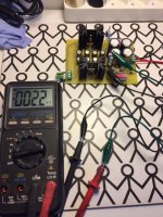
Near 5mA even in a difficult scale of V for few mV with DMM tolerance. All is well.
Yep...
Hope You All enjoy Friday evening as i do?
Cheers / Jesper
Hi.
This morning i tried to load the DCSTB a little by 320ohm power resistor, at each side of rail. Positive side, dropped from 17.23 into some 17.17, the same on negative rail. -At moment i have no oscilloscope sadly so cannot look at ripple etc...
How much voltage (if any?), must i expect when PSU(s) are loaded with Preamp, when times come ?
Jesper.
0.06V of sag is quite low for connecting an amplifier to an unloaded PSU.
I'd expect maybe around a volt of sag due to the quiescent current of the amplifier.
A power amplifier with a high bias could result in a 2 to 3Volt drop when connected.
You can measure supply rail ripple with your DMM set to AC volts.
But some DMM do not tolerate DC while measuring AC. You would need to add a DC blocking capacitor to this type to prevent you damaging the meter.
I have 4 different DMM and all of my types can tolerate quite high DC voltage and still measure AC voltage on the 199.9mVac scale (even on a 50Vdc rail).
The DMM measures an ac equivalent. The ripple peak to peak is roughly three times the meter reading, i.e. Vpp ~ 3*Vac
I have confirmed this numerous times by comparing to the scope trace.
Last edited:
Thanks again Salas. There is much thought behind this design, I bet it cost you much more time to design it that I can imagine.
It looks very high-endish, I love it! I'll be building it for sure to use it as a headphone amplifier.
I'll give it a try on a prototype PCB board. What about replacing the current mirror JFETs with sk117/170?
There will be also a socket for the servo chip for sure, because from subjective experience these contribute to the total sound quality of the device.
It will be also built with my favorite choke input filtering power supply. I'll give you a feedback when it's done.
0.06V of sag is quite low for connecting an amplifier to an unloaded PSU.
I'd expect maybe around a volt of sag due to the quiescent current of the amplifier.
A power amplifier with a high bias could result in a 2 to 3Volt drop when connected.
You can measure supply rail ripple with your DMM set to AC volts.
But some DMM do not tolerate DC while measuring AC. You would need to add a DC blocking capacitor to this type to prevent you damaging the meter.
I have 4 different DMM and all of my types can tolerate quite high DC voltage and still measure AC voltage on the 199.9mVac scale (even on a 50Vdc rail).
The DMM measures an ac equivalent. The ripple peak to peak is roughly three times the meter reading, i.e. Vpp ~ 3*Vac
I have confirmed this numerous times by comparing to the scope trace.
Thanks AndrewT
This is nice to know...
Jesper.
Hey all here!
I would like to share my own pcb layout here, but i don't want if anybody think that is the case to spoil this threat?
Reason i would share it, is that somebody might have good eyes, and maybe giving me some corrections? - Who knows, it could might well be corrected to something better looking or so.
What do you think guys ?
Jesper.
You should make your own thread so that there is no confusion when people need help with stuff and use the reference " the resistor next to cap 100uf" or "close to this and that part". The cercuit might be the same, but the layout is not so don`t mix different pcb`s in the same thread.. Just my 2cents..
You should make your own thread so that there is no confusion when people need help with stuff and use the reference " the resistor next to cap 100uf" or "close to this and that part". The cercuit might be the same, but the layout is not so don`t mix different pcb`s in the same thread.. Just my 2cents..
Nice answer... i think you are right!
Jesper.
Thanks again Salas. There is much thought behind this design, I bet it cost you much more time to design it that I can imagine.
It looks very high-endish, I love it! I'll be building it for sure to use it as a headphone amplifier.
I'll give it a try on a prototype PCB board. What about replacing the current mirror JFETs with sk117/170?
There will be also a socket for the servo chip for sure, because from subjective experience these contribute to the total sound quality of the device.
It will be also built with my favorite choke input filtering power supply. I'll give you a feedback when it's done.
Both 2SK117 and 2SK170 Toshiba as well as LSK170 Linear Systems work as LTP in this circuit. 2SK170 has more Ciss so it would rather be better with 20K pot. It will also give only about 0.0002% THD at 1.2Vpp 1kHZ. Although it won't be better in HF than the others despite of its higher Yfs due to its capacitance. It will show a more pronounced rising trend due to its lower median THD and bit more IMD. With the uPA I had measured the -3dB bandwidth at 1MHZ for 20K pot and 500kHZ with 50K pot (both when at half value position).
I have taken part to the group buy for complete sets of the preamp and PS units. I'm planning to use Vicol Audio's R-2R stepped attenuator as a volume controller for DCG3. I'm just wondering which would be the correct constant output impedance value to use when feeding the DCG3? 20k? I'm using this calculator: Logarithmic Attenuator Calculator to calculate the R-2R resistor values.
These multi-relay attenuators place many switches in the current paths.
You will find many here that think removing one switch from the attenuator gives an improvement in the transparency of the equpment.
I'm pretty sure those same Members would frown on adding 8 switches where one could manage with one.
Then one might want to consider adding 20 something extra soldered joints compared to using only 4 soldered joints. Is this an improvement?
Last edited:
I did not test with less than 20K pot in this case. For almost any source equipment not to be challenged for driving or coupling to a more difficult low impedance. Like highish output Z valve phonos, some I to V etc. 20K to 50K is the rangeI tested and I can say all was stable and the tone was good. For other ranges better test with a cheap pot first before investing in a high quality pot.
Salas, is there any advantage to matching M1 between channels?
Thanks. nash
M3 for certain. BC560's for certain.
M3 for certain. BC560's for certain.
Agreed. I was just wondering whether two unmatched M1's having different gain characteristics could be less than optimal and so a match would be a good idea? I dont suppose matching M2 matters since it is acting as a cascode. Just trying to understand this better.
nash
- Home
- Source & Line
- Analog Line Level
- Salas DCG3 preamp (line & headphone)