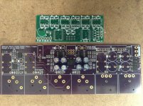
I am talking about the VolCB board
In Posting #60 there is a dropbox link.
In the BOM for the VolCB there is some comment below, telling that you can place the VolCB on top of the BPBP through a 2x3 pin header and connector, or alternatively use solid wires and solder both PCB's to these wires.
Even firmer is to use a 2x3 Board to Board connector with pins that are long enough. Farnell has a huge assortiment to select from.
The way to connect both PCB's can be seen on the illustration, also provided in the dropbox link.
I have used an angled board to board connector, so the VolCB is standing upright before the BPBP.
The VolCB board is as light as a feather, so when connected correctly to the BPBP, it does not need extra support in normal use.
Hans
Just finished building the BPBP. I've not assembled the VolCB board yet so I installed the pot on the BPBP for now to keep things simple.
When the pot is turned all the way up I measure 11.15 vdc on the hot output of one channel and -11.15 vdc on the other channel. Throughout the lower and midrange of the pot DC levels are fine. Sounds kind of weird to me. Is this normal? I have no inputs or outputs connected.
When the pot is turned all the way up I measure 11.15 vdc on the hot output of one channel and -11.15 vdc on the other channel. Throughout the lower and midrange of the pot DC levels are fine. Sounds kind of weird to me. Is this normal? I have no inputs or outputs connected.
Just finished building the BPBP. I've not assembled the VolCB board yet so I installed the pot on the BPBP for now to keep things simple.
When the pot is turned all the way up I measure 11.15 vdc on the hot output of one channel and -11.15 vdc on the other channel. Throughout the lower and midrange of the pot DC levels are fine. Sounds kind of weird to me. Is this normal? I have no inputs or outputs connected.
This happend because gain is set to infinity.
One of the things that can never happen with the VolCB.
Never turn the pot further than ca 65%, gain is in that case 6dB.
Hans.
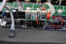
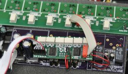
After assembling the VolCB and 4 input boards I hooked them up to my existing Maya controller. When power was applied to the Maya the display remained blank except for a blinking cursor at the left. After about 5 seconds I noticed a wisp of smoke and quickly cut power.
Hans, Please take a look at the attached pictures. This was how things were hooked up. Do you see anything improper. I am reluctant to try this again.
Thanks, Mike
Hans, Please take a look at the attached pictures. This was how things were hooked up. Do you see anything improper. I am reluctant to try this again.
Thanks, Mike
Attachments
After assembling the VolCB and 4 input boards I hooked them up to my existing Maya controller. When power was applied to the Maya the display remained blank except for a blinking cursor at the left. After about 5 seconds I noticed a wisp of smoke and quickly cut power.
Hans, Please take a look at the attached pictures. This was how things were hooked up. Do you see anything improper. I am reluctant to try this again.
Thanks, Mike
Hi Mike,
There are two things that I can see that are wrong.
1) On the VolCB U1 is mounted the wrong way because it is 180 degrees turned, this is a serious error.
2) The two wires leaving the right bottom corner from the VolCB should have been connected instead to J13/Switch BPBP from the 4 input select board. This is a harmless error, but will have to be corrected.
So you will have to renew U1 and connect J13, and hopefully everything will work.
Hans
I don't quite understand #2. Should the switch wires go from VolCB to the 4 input board? or from BPBP to the 4 input board? The input selection relay on the BPBP needs to be switched, right?
I don't quite understand #2. Should the switch wires go from VolCB to the 4 input board? or from BPBP to the 4 input board? The input selection relay on the BPBP needs to be switched, right?
When using the VolCB only, the wires go as you have routed them now, and a relay on the same spot as where you have placed the header from the flat cable will do its job in selecting one of both inputs.
But when using a 4 input select board, switching of the relay on the BPBP board is effectuated from J13 on the 4 input select board.
The two connections on the VolCB in your case are connected to nothing, what you can see when looking at the PCB layout.
Hope you can remove U1 without damaging the PCB.
Succes and feel free when you have further questions to ask.
Hans
Happy to hear that everything seems to be working so far.OK, I understand. Wires go from J13 on the 4 input board to the BPBP.
I have removed and replaced U1 (using Chipquick) and all seems to be working. No signals are hooked up yet but I hear relays clicking for volume and input selection.
Appreciate your help!
Mike
Chipquick is completely new to me.
I watched the video and it seems an amazing help in de-soldering SMD's.
Hans
Hi Hans,
When are you expecting to finish to test Maya + VoICB firmware?
Thanks
Do
Hi Do,
As I have already mentioned in the group buy forum, Tibi has shipped the boards to me July the 27th.
Unfortunately I haven't received them so far and Tibi is pushing the expedition company.
I only need one or two days, but all I can do is wait and wait.
The moment I get boards, I will inform everybody.
I'm very sorry, but there is not much that I can do at the moment.
Hans
Happy to hear that everything seems to be working so far.
Chipquick is completely new to me.
I watched the video and it seems an amazing help in de-soldering SMD's.
Hans
Chipquick works very well. It seems a bit expensive but its worth it. A little goes a long way.
Today I wired up the inputs and outputs to the BPBP/VolCB/Maya combo. The volume control works very well. The 4 input selection is not working for me with the Maya. I am using firmware 1.9. I may not have things hooked up correctly though. I have the output of the 4 input board going to input 2 of the BPBP (the one when the relay in grounded).
- Status
- This old topic is closed. If you want to reopen this topic, contact a moderator using the "Report Post" button.
- Home
- Source & Line
- Analog Line Level
- Remote Control for the BPBP