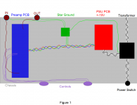
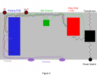
Hi everyone, I am trying my best to understand ground loops and send and return paths to achieve the lowest noise possible but I feel like I am retarded sometimes because I still don't fully understand. Is one of these figures better than the other or are they both wrong?
Also, I am planning on using 18 gauge wire for all of the internal connections shown. Is this too heavy of a gauge because it will have too much capacitance? My project box is 16"(41cm) x 8"(20cm) to give you an idea of the lengths of wire for connecting the PCBs.
Also, I am planning on using 18 gauge wire for all of the internal connections shown. Is this too heavy of a gauge because it will have too much capacitance? My project box is 16"(41cm) x 8"(20cm) to give you an idea of the lengths of wire for connecting the PCBs.
Attachments
I'd put the rings/shafts of the input jacks to ground near the power supply of the op amps or transistors receiving the signal. there should be some sort of common mode rejection mechanism there to reduce hum. then let the power supply of the preamp board go to the star ground.
Put a steel bulkhead around the power transformer and keep the 120 VAc stuff entirely out of the case of the preamp . Like a dynaco PAS2 is two boxes, a 120 vac box and a signal box, all inside one case. I spent months chasing hum in a badly packaged mixer, finally going to a wall transformer outside the case, and no AC switch.
If you've got a turntable, the star ground point is the headshell ground terminal on the back of the case. The one for the green wire from the turntable.
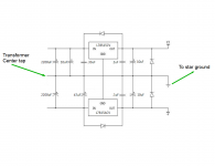
transformer gnd? - if you mean secondary Center Tap - that should just go to the PS reservoir Caps gnd junction
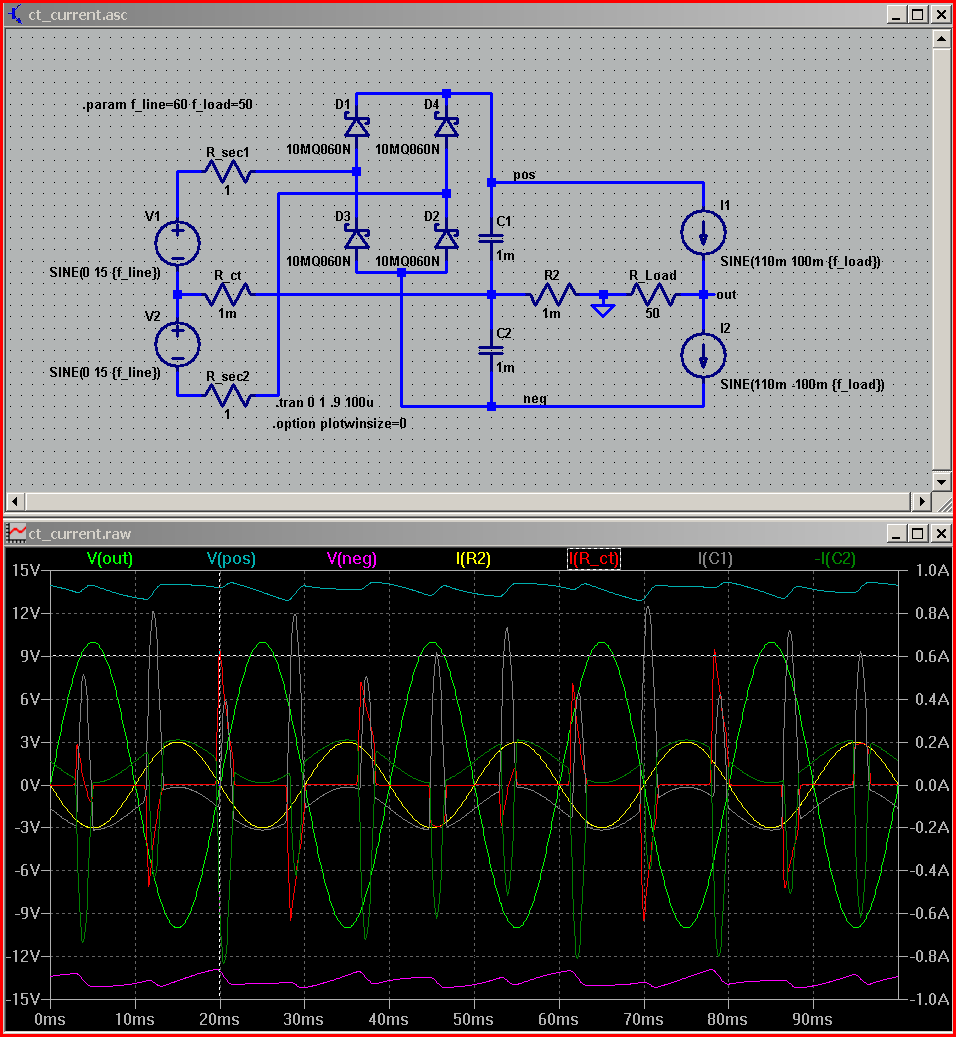
busy sim but maybe helpful
left side sims xfmr secondary - see that I put the gnd on the other side of the reservoir C junction
busy sim but maybe helpful
left side sims xfmr secondary - see that I put the gnd on the other side of the reservoir C junction
yes a "star", by itself, is exactly a "too simple" idea
hierarchical grounding, "dirty"/"clean" branch separation are important ideas too
and like DF says - CT to reservoir cap junction is "dirty" - has rectified charging current pulsing in the wire, creating nasty nonlinear Vdrop in its R,L
the mains xfmr secondary is floating, the isolation should be taken advantage of by letting it be an "open" end of the dirty current branch
at the very least the location of the "star" point can be chosen for better or worse performance - and worse would be the xfmr CT
I'd put the rings/shafts of the input jacks to ground near the power supply of the op amps or transistors receiving the signal. there should be some sort of common mode rejection mechanism there to reduce hum.
You mean common mode rejection from the op amps on the preamp board and that they won't be effective if the in's ground goes straight to star?
transformer gnd? - if you mean secondary Center Tap - that should just go to the PS reservoir Caps gnd junction
The first image is what I have ready to go now (the one on the left). Is this proposed image (on right) going to be better for noise?
"the mains xfmr secondary is floating, the isolation should be taken advantage of by letting it be an "open" end of the dirty current branch"
I don't understand this. Does it mean leave the center tapped disconnected?
Attachments
The center tap of the transformer, if you're using op amps, is connected to the regulator board center, then the input board signal ground. The rings of the input jacks refer to that. You want that isolated from the safety ground of the wall socket. If you're not using a turntable and phono cartridge, you'll put something like a 10k ohm resistor parallel .047 cap between op amp power supply ground and safety ground. That will prevent static buildup if any component has any leakage current .
I don't understand this. Does it mean leave the center tapped disconnected?
You must connect the center tap or the supply won't work.
I work with mic level input signals all the time. This is how I do my wiring.
IEC AC Ground - this is the safety ground, connect to metal case immediately, right near the IEC AC inlet.
Transformer Center-tap - connect to PSU PCB.
PSU output ground - connect to preamp board
Audio Input and Output XLR jacks - connect ground (pin1) via wire to preamp PCB.
Audio Input and Output XLR jacks - also, short pin1 to metal body case of XLR jacks, which is then screwed to the metal case, and making electrical contact with the case... effectively grounding the case
Any noise coming externally via the input or output XLR jacks are immediately shunted to ground/metal case right at the entrance.
The only "wire" I have connected to the metal case is the safety ground from the IEC AC inlet connector.
This scheme has proven to be very quiet, even with the input signal amplified to 72dB gain (4000x amplification).
Bonus: Use a toroid transformer, and rotate toroid a few degrees left or right to find the sweet spot where hum/noise is the minimum. (of course, unit is powered on and you're listening to the output noise via a connected speaker). Once the sweet spot is found, turn off power and tighten bolt on toroid transformer.
Thank you for your info. I am not using a safety ground. I also don't have a ground plane on my preamp PCB, that is why I was sending all grounds to the star point which is a copper plane attached to chassis.
Is the star ground not the way to go for preamp signals or something like that?
Is the star ground not the way to go for preamp signals or something like that?
.
<< I am not using a safety ground. >>
I very strongly recommend that you do. Or don't let the kids within a mile of the thing.
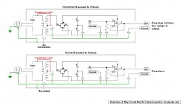
The post below is intended to show the possible result of not having both the circuit and the housing grounded (the safety ground). The green line is not present as an actual wire, but it does exist electrically, since ultimately all grounds are the same ground.
If your local supply voltage is 120 volts, that voltage will knock you across the room but might not kill you. In countries where the supply voltage is 220, results can be grim.
<< I am planning on using 18 gauge wire for all of the internal connections >>
On a happier note, using #22 or #24 wire is fine until you get to the output. Output wires must be sized to carry the expected wattage, and so must power supply wires, of course. #18 is probably fine.
.
<< I am not using a safety ground. >>
I very strongly recommend that you do. Or don't let the kids within a mile of the thing.
The post below is intended to show the possible result of not having both the circuit and the housing grounded (the safety ground). The green line is not present as an actual wire, but it does exist electrically, since ultimately all grounds are the same ground.
If your local supply voltage is 120 volts, that voltage will knock you across the room but might not kill you. In countries where the supply voltage is 220, results can be grim.
<< I am planning on using 18 gauge wire for all of the internal connections >>
On a happier note, using #22 or #24 wire is fine until you get to the output. Output wires must be sized to carry the expected wattage, and so must power supply wires, of course. #18 is probably fine.
.
Attachments
.
As you see, asking about grounding is opening a can of worms. There are different theories.
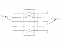
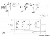
Here's my understanding of the right way to do it, based on some references from Texas Instruments, Douglas Self, and others. The NE5532 circuits shown are arbitrary, they're just there to provide something to connect to ground.
The real concern is to avoid mixing noisy power supply voltages with the audio signal. Of course you have to mix them at the power supply transformer center tap, which is the ultimate ground where everything comes together, but keep them separated otherwise.
The basic idea is that wire is not the perfect conductor we'd like. Both wire and the metal housing do have resistance, which creates micro-voltages and current flows that we'd rather not have because they're noise. This is the noise we want to keep away from the audio signal.
.
As you see, asking about grounding is opening a can of worms. There are different theories.
Here's my understanding of the right way to do it, based on some references from Texas Instruments, Douglas Self, and others. The NE5532 circuits shown are arbitrary, they're just there to provide something to connect to ground.
The real concern is to avoid mixing noisy power supply voltages with the audio signal. Of course you have to mix them at the power supply transformer center tap, which is the ultimate ground where everything comes together, but keep them separated otherwise.
The basic idea is that wire is not the perfect conductor we'd like. Both wire and the metal housing do have resistance, which creates micro-voltages and current flows that we'd rather not have because they're noise. This is the noise we want to keep away from the audio signal.
.
Attachments
Last edited:
I understand. This is only a preamp, it won't draw more than 200mV on the secondary side. Not worried about the transformer failing like that. Most AVRs (which send a lot more power out of them than this thing) are not safety grounded in America and I haven't heard of any deaths/injuries from them.
I am only concerned with noise and wiring this thing to make it as quiet as possible but I am too dumb to know how.
I am only concerned with noise and wiring this thing to make it as quiet as possible but I am too dumb to know how.
.
<< Not worried about the transformer failing... >>
All machines fail, the only question is when.
<< Most AVRs (which send a lot more power out of them than this thing) are not safety grounded in America... >>
I don't know what an AVR is, but if they're not either double-insulated or grounded, then they didn't pass Underwriters Laboratories inspection, which in some jurisdictions makes it illegal to sell them.
<< I haven't heard of any deaths/injuries from them. >>
Some 40,000 people are killed every year in traffic accidents in the USA. How many of them do you hear about?
Well, best of luck to you.
.
Last edited:
Well no....................................
Audio Input and Output XLR jacks - connect ground (pin1) via wire to preamp PCB.
Audio Input and Output XLR jacks - also, short pin1 to metal body case of XLR jacks, which is then screwed to the metal case, and making electrical contact with the case... effectively grounding the case
Any noise coming externally via the input or output XLR jacks are immediately shunted to ground/metal case right at the entrance.
.............................................
Audio Input and Output XLR jacks - connect ground (pin1) via wire to preamp PCB.
This is incorrect. There is no wire to the preamp PCB.
Audio Input and Output XLR jacks - also, short pin1 to metal body case of XLR jacks, which is then screwed to the metal case, and making electrical contact with the case... effectively grounding the case
Not sure just what this means.
But each XLR pin1 is only connected to the chassis at the connector.
Ground has nothing to do with it. XLR pin1 is only a shield.
Any noise coming externally via the input or output XLR jacks are immediately shunted to ground/metal case right at the entrance.
Shunting has nothing to do with it. You are just extending the shield.
In any case, noise has little interest in ground.
.
<< Not worried about the transformer failing... >>
All machines fail, the only question is when.
<< Most AVRs (which send a lot more power out of them than this thing) are not safety grounded in America... >>
I don't know what an AVR is, but if they're not either double-insulated or grounded, then they didn't pass Underwriters Laboratories inspection, which in some jurisdictions makes it illegal to sell them.
<< I haven't heard of any deaths/injuries from them. >>
Some 40,000 people are killed every year in traffic accidents in the USA. How many of them do you hear about?
Well, best of luck to you.
.
Transformers sometimes fail and when they do, they go open, they don't short the primary to the secondary, that's why it's called an isolation transformer. AVR is an audio video receiver. Manufacturers submit products to UL for testing and safety certification on a voluntary basis, it isn't a gov't requirement. My tranny is double insulated by the way.
Even if somehow my chassis came in contact to the hot mains leg, it will be connected with xlr to an amp with it's chassis grounded to mains earth so the breaker would trip.
Everyone ignore this and get back on topic please because this has nothing to do with the help that I need. Snake, I appreciate your 2nd post pertaining to my thread but I don't need fire marshal bill's design tips.

If you are going to build mains powered equipment, it must at least comply to safety regulations.
Advising others to ignore safety regulations, could make you responsible for their damages.
Electrifying Sound is not the way to go!
Advising others to ignore safety regulations, could make you responsible for their damages.
Electrifying Sound is not the way to go!
Last edited:
It is perfectly legal where I live so I am. Seriously though, does anyone have the answer to my problem instead of being my life coach?
Star ground should be on the PSU board, at one of the capacitor terminals. You can connect one wire to the chasis from there.
The GND for IN should be connected to the circuit ground at the input terminals(of the opamp or anything that forms the active component in the preamp) and not to the star ground, and certainly, should be isolated from chasis.
Gajanan Phadte
The GND for IN should be connected to the circuit ground at the input terminals(of the opamp or anything that forms the active component in the preamp) and not to the star ground, and certainly, should be isolated from chasis.
Gajanan Phadte
Star ground should be on the PSU board, at one of the capacitor terminals. You can connect one wire to the chasis from there.
The GND for IN should be connected to the circuit ground at the input terminals(of the opamp or anything that forms the active component in the preamp) and not to the star ground, and certainly, should be isolated from chasis.
Gajanan Phadte
Are you saying that the PSU ground and the signal in/outs ground should have no continuity with each other?
- Status
- Not open for further replies.
- Home
- Source & Line
- Analog Line Level
- Which one of these wiring schemes will have lower noise?