Your transistors measure close to equal Vbe whereas mine measured close to 60mV different - so it wouldn't be a good idea to try and copy my results.
For one thing I don't know about DACs. I don't know whether current mode or voltage mode is better or for what reasons. I'd appreciate links to app notes on this topic.
Most of the time it's not a good idea to try to force an unbalanced circuit to use balanced input. You usually don't get much of the benefits and end up having worse performance.
So for a balanced circuit you would want to use 2 kuartlotrons.
The Kuartlotron doesn't have any very useful internal nodes like you would expect in a feedback circuit. This is because every node in the Kuartlotron is already used for distortion cancellation and disturbing that will lead to reduced performance.
I was hoping in using this buffer for my DAC's balanced output.
I have no idea how to use 2 kuartlotrons for my application. Could you make a drawing?
Thank you
I have no idea how to use 2 kuartlotrons for my application. Could you make a drawing?
Thank you
I was hoping in using this buffer for my DAC's balanced output.
I have no idea how to use 2 kuartlotrons for my application. Could you make a drawing?
Thank you
This will depend on your DAC. The kuartlotron is a buffer, so it does not provide voltage gain. Therefore, your DAC would need to already produce the full desired signal voltage amplitude. Does your DAC produce a voltage output?
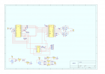
Oh yes. In fact here's the schematic. It currently uses an op-amp with unity gain on the output, and I wish to bypass that with the kuartlotron buffer. The differential voltage output is about 2.5V.
The schematic is for AK4393 and my DAC uses AK4396 but it's the same schematic for both.
The schematic is for AK4393 and my DAC uses AK4396 but it's the same schematic for both.
Attachments
I need to measure that. But I guess it's 2.5V between the balanced pins of the chip on each channel, not relative to ground. But I can measure each pin vs ground.
I need to measure that. But I guess it's 2.5V between the balanced pins of the chip on each channel, not relative to ground...
Okay, here's my brief assessment. If you place a kuartlotron after the op-amp you will retain the full signal output amplitude of about 2VRMS. However, the purpose of the op-amp is to convert the differential DAC outputs to a single-ended output. Which means that each phase of the DAC outputs is only half the amplitude of the single-ended op-amp output. Therefore, should you want to eliminate the op-amp, you would be limited to using only a single kuartlotron that's connected to one of the DAC's two output phases (per channel, of course). The end result would be a single-ended signal of only half the amplitude than if using the op-amp, or about 1VRMS. In addition, that 2.5VDC common-mode bias offset will need to be blocked with a capacitor, which would be most conveniently located at the output of the kuartlotron.
Last edited:
It is possible to make the negative DAC output a virtual ground for the Kuartlotron (which would run on an isolated trafo winding), creating a full-voltage unbalanced output, but in practice I don't like PSU bootstrapping like this because it sends ground noise into the circuitry. It could be worth trying with a CM choke in a strategic position though.
Rather orgasmic to be able to crank up your system loud without the blare.
Link: Kean's common mode choke
Link: Kean's common mode choke
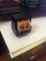
I found a CM choke in a failed computer PS. It looks identical as the one in the link only that it measures about 10mH on each winding. Would that do? I saw that a 20mH one is recommended. I could look for some more as I have access to some failed computer PS.
I might try this over the weekend if I get some spare time.
I might try this over the weekend if I get some spare time.
Attachments
Last edited:
The effect should be audible down to a few mH because at 1KHz the fault rejection is much higher than at 60Hz (it doubles every octave) . Of course you may not hear a difference if you don't have ground noise problems, but I think it's very unlikely you don't have any ground noise.
The benefit of a large choke is that it has more of an effect in the bass, to my ears. 10mH will be no worse than a 5R groundlift resistor, which isn't bad. I'm using 15mH right now, since it's the largest I have. 5mH is enough to significantly reduce 60Hz ground fault current.
The benefit of a large choke is that it has more of an effect in the bass, to my ears. 10mH will be no worse than a 5R groundlift resistor, which isn't bad. I'm using 15mH right now, since it's the largest I have. 5mH is enough to significantly reduce 60Hz ground fault current.
Does this mean you want to try the virtual ground bootstrap, or do you have another plan? Either way, the CM choke could be helpful.
I'm playing around with the same DAC chip (AK4396), and I'm willing to try out using the virtual ground bootstrap idea. 🙂
Have most of the parts lying around in my spare bin, with the exception of the 2700k pot, 15pF cap, and the inductor.
EDIT : If I were to use this to implement a low pass filter as well as the bal -> se conversion, would it be just as simple as placing the components across the + - legs? Or should there be one set each of low pass filter components for both + and - legs, connected to ground?
Last edited:
Does this mean you want to try the virtual ground bootstrap, or do you have another plan? Either way, the CM choke could be helpful.
Yes, I'd try the virtual ground bootstrap. I have the inductor and need to source the transistors, but should be ok. I might go to the store today. Any idea on how to test those transistors for better matching with dmm/oscilloscope? 🙂
I found a CM choke in a failed computer PS. It looks identical as the one in the link only that it measures about 10mH on each winding. Would that do? I saw that a 20mH one is recommended. I could look for some more as I have access to some failed computer PS.
I might try this over the weekend if I get some spare time.
The following caveat should be mentioned regarding the use of common-mode chokes in a signal coupling application. Common-mode chokes exhibit leakage inductance. This leakage inductance will appear as a normal-mode impedance. In other words, it will impede the desired normal signal conduction. This is a useful parasitic effect in power supply applications, where you then obtain common-mode noise choking, plus some small amount of bonus normal-mode noise choking from the same component.
Although this leakage inductance will be a small fraction of the common-mode inductance, in conjunction with the interconnect's and the following stage's shunt input capacitance, it will produce an unintended second-order low-pass filtering of the signal. Before selecting the specific common-mode choke you will use, you should compute how this unintended low-pass filter will impact the desired signal's frequency response. If you are clever and lucky, you could engineer this unintended filter to help reject the ultrasonic image and noise content produced by your DAC.
You should find the leakage inductance specified in the common-mode choke's datasheet.
Last edited:
The following caveat should be mentioned regarding the use of common-mode chokes in a signal coupling application. Common-mode chokes exhibit leakage inductance. This leakage inductance will appear as a normal-mode impedance. In other words, it will impede the desired normal signal conduction. This is a useful parasitic effect in power supply applications, where you then obtain common-mode noise choking, plus some small amount of bonus normal-mode noise choking from the same component.
Although this leakage inductance will be a small fraction of the common-mode inductance, in conjunction with the interconnect's and the following stage's shunt input capacitance, it will produce an unintended second-order low-pass filtering of the signal. Before selecting the specific common-mode choke you will use, you should compute how this unintended low-pass filter will impact the desired signal's frequency response. If you are clever and lucky, you could engineer this unintended filter to help reject the ultrasonic image and noise content produced by your DAC.
You should find the leakage inductance specified in the common-mode choke's datasheet.
That is good info, thank you! I'm learning lots from you guys!
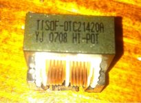
I typed on google the codes on this choke but nothing came up. If I can't find the datasheet I'm going to take the data from the one posted already. I saw that there are 10mH versions for that as well so they might have similar specs. Or anyway, not far off.
Attachments
That is good info, thank you! I'm learning lots from you guys!
I typed on google the codes on this choke but nothing came up. If I can't find the datasheet I'm going to take the data from the one posted already. I saw that there are 10mH versions for that as well so they might have similar specs. Or anyway, not far off.
If you cannot locate the datasheet, you could go forward and find whether you subjectively notice any treble roll-off effects. If you do not, then no worries. However, common-mode chokes of the values being discussed are relatively inexpensive. You could simply purchase new units having the desired properties, rather than re-purpose mystery units from a PC power supply. If this choke were simply to be used within your DAC's power supply, I would feel less concerned. Seeing that it will be placed in the signal path, however, I suggest extra care in applying it.
You should find the leakage inductance specified in the common-mode choke's datasheet.
One can also measure the leakage inductance of an unknown CM choke, by shunting one coil and measure the other.
- Home
- Source & Line
- Analog Line Level
- The Kuartlotron - keantoken's simple error-correction superbuffer