Two 160VA trafos, nothing more required......
Hugh
Hugh,
Is 1 25VAC x2 300VA transformer ok?
PS question
My boards are populated with the exception of the auricap which has yet to arrive. I intend to use a single transfomer (which i have) 400va with two 25v secondary windings. This is what have and budget wont allow twin transformers. Are there any grounding factors that might plague me with this approach ??Also when setting the bias it's 11-14 ma on the VAS and 400ma outputs??!!Is it a good idea to include inrush suppressors in the PS.
I've been building class A stuff so long I've forgotten all the rest !!
Thanks again for your superb effort to get us to this great project.")
My boards are populated with the exception of the auricap which has yet to arrive. I intend to use a single transfomer (which i have) 400va with two 25v secondary windings. This is what have and budget wont allow twin transformers. Are there any grounding factors that might plague me with this approach ??Also when setting the bias it's 11-14 ma on the VAS and 400ma outputs??!!Is it a good idea to include inrush suppressors in the PS.
I've been building class A stuff so long I've forgotten all the rest !!
Thanks again for your superb effort to get us to this great project.
Hi Syklab,
No problem, larger trafos are OK and will work well.
However, if you use ONE transformer, you should take just one simple precaution.
On a single 25-0-25Vac trafo you have two (2) independent secondaries, secondary #1 and secondary #2, both identical.
Keep them completely separate, that is, no center tap.
Now, connect secondary #1 to the POSITIVE supply on the left channel, and using wire extension to give four wires instead of just two, also to the POSITIVE supply on the right channel.
The other secondary, #2, again using wire extensions, should be connected to the NEGATIVE supply on the left channel, and the NEGATIVE supply on the right channel.
This way there will be no earthing conflicts.
A 300VA single transformer is fine for this amp - it's only 50W per channel after all - and even two 300VA trafos will work fine. But the minimum size per channel would be around 120VA, with 160VA being best of all.
There have been some sporadic reports of this amp saying it's genuinely high end. I'm very pleased about this, that's how I see it too!
Sandyhooker, my thanks for your thanks. I do feel Greg, Swordfishy, should get the credit, however. I just did the pcb.
Cheers,
Hugh
Kudos
Sorry not to have included Greg while offering my appreciation for this project.He has been very responsive to questions I posed and of the many who added to the development of this amplifier he was most prominent.
I originally became interested in this due to its unique concept as well as its satisfaction of a need to find a cooler appliance than my F5 .I live in a desert where the temps are extreme.
It is cooler now so the pressure to replace the F5 is not so great .Still, I am quite anxious to hear the results of all your efforts.
JT Perkins
Yes, there are strong similarities between Phoenix (?) temperatures and our inland towns in Oz. Alice Springs comes to mind. I remember as a young man reading about an imaginative building design in Phoenix which extended several floors below ground, where it was cooler and expensive air conditioning was not required. But lighting was an issue, so a large vertical atrium of mirrors was created to capture sunlight and beam and diffuse it to the floors below ground.
My understanding is that daytime temperatures can easily exceed 50C (122F). Correct?
That's hot...... but Melbourne a couple of years ago took a hit on a day of huge bushfires, we hit 48C, and that was hot too......
Cheers,
Hugh
My understanding is that daytime temperatures can easily exceed 50C (122F). Correct?
That's hot...... but Melbourne a couple of years ago took a hit on a day of huge bushfires, we hit 48C, and that was hot too......
Cheers,
Hugh
Hi Hugh,
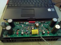
Well, I'm completely stumped. I have cooked resistors R22/24 on two seperate attempts to power the boards. My transformer is 30-0-30 plus a 15vac tap. I hooked the yellow wires one each to the SEC #1A and #2A tabs, and the blue wires to the #1B and #2B tabs. I left the fuses F1 and F2 open and removed resistors R20&21. I connected the chassis ground to the board The spkr cold and output were left un-connect. I used BYV32 diodes. I've compared the polarity of all my caps with your board photos. I can't for the life of me figure out what I'm doing wrong. Any/all help would be appreciated.
Regards,
Ken
Attachments

Last edited:
Ken,
First, your rail voltage is too high; 30Vac secondaries will generate more than 42V rails, not the 36V rail this amp is designed for. So that's one issue.....
Second, I think you have an earthing conflict. It looks to me that rather than connect one secondary to the positive rail (Secondary #1) and the other to then negative rail (Secondary #2) you have connected one lead of each secondary to the positive rail, the other to the negative rail supplies. This will take out R22 and R24 everytime as there will be a conflict across ground.
Check your secondaries again...... fortunately only resistors need replacement.
Cheers,
Hugh
Ken,
First, your rail voltage is too high; 30Vac secondaries will generate more than 42V rails, not the 36V rail this amp is designed for. So that's one issue.....
Second, I think you have an earthing conflict. It looks to me that rather than connect one secondary to the positive rail (Secondary #1) and the other to then negative rail (Secondary #2) you have connected one lead of each secondary to the positive rail, the other to the negative rail supplies. This will take out R22 and R24 everytime as there will be a conflict across ground.
Check your secondaries again...... fortunately only resistors need replacement.
Cheers,
Hugh
Thanks for the help. I hooked it up to my own DC power supply, and it runs great. I will prepare a a simple drawing in the next few days of what I believe you (Hugh) are recommending to make sure I have it right before hooking it up again.
Andrew, I did use a bulb tester initially and it wasn't glowing full bright. But you know, smoke and flames add interest to the evening. It ended up to be a good reason for full strength margaritas, especially since my wife was making chili verde!
Ken
Ken
It looks to me that you have problem that is related to your transformer connection. Just make sure that there is no physical connection between secondaries by using ohmmeter. When you verify that transformer is OK then go to your bridge diodes and check the polarity. Try to connect your transformer without any connection to the chassis ground first and see if it works.
George
Ken,
George is on the money; I described it as an earthing conflict, but in truth his description is more apt. You effectively have one secondary fighting the other, across one of the two resistors between the filter caps.
Solution: Identify EACH secondary wiring, start and finish. Connect one secondary, #1, start and finish, to the two AC inputs Sec #1A and Sec #1B, on BOTH pcbs if you are using just one trafo for both. Then connect the other secondary, #2, start and finish, to the two AC inputs Sec #2A and Sec #2B, on BOTH pcbs if you are using just one trafo for both.
The order of 'start and finish' is not important. What is important is that, IF USING ONE TRAFO, one secondary supplies the POSITIVE RAIL of BOTH CHANNELS, and the other secondary supplies the NEGATIVE RAIL of BOTH CHANNELS.
Hope this helps,
Hugh
Last edited:
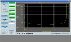
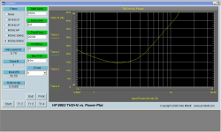
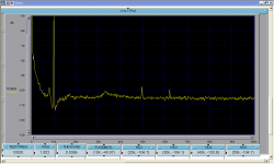
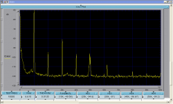
I will still make a drawing for review prior to trying again. With the amp hooked up to my existing supply which makes +- 32vdc and 58,000uf capacitance I ran one channel for the day. Set the bias at 130mV warm. The sound is very nice, open and clean. I made the following tests using an HP8903A, which seems a bit pessimistic on the 10k values. I also ran some 10k spectrum plots as well. Note that these plots are with a twin-t null of about 50db and fed through an attenuator to have the voltage at the spectrum analyzer 1vrms/0db. With the amp making 1vrms at 10kHz, the harmonics are at or below the noise floor of the analyzer.
Ken
Ken
Attachments

Ken,
I'm seeing very high THD + noise here; 0.9% up to 1.8%, is this correct?
I'm surprised it's so high, perhaps some interpretation is in order since you are saying distortion is also below the noise floor at 10KHz and this is, we know, a very quiet amp?
Thank you for taking such trouble to measure it, Paul Bysouth has also done some measurement recently on his two monobloc FetZillas and has some very good results.
Enjoy that Marguerita, but go easy on the salt....
Cheers,
Hugh
I powered up my first board today but used a light bulb in series with the mains to start with.
I can get 37mv across R17 by adjusting P1. However, I can't get 26V across R12 by adjusting P3. But if I turn P1 down so that there's 27mv across R17 then I can get 26V on P12. I wonder if this is because the light bulb is in circuit. Which by the way is glowing very softly. Is it safe to remove the light bulb now and see if I can adjust the pots? I'm just a bit worried about frying everything. The two LEDS are glowing and I'm measuring +/- 27V on the fuses.
When I first powered up there was about 700ma bias. As I turned that down the light bulb got dimmer. So I'm guessing that the bulb is restricting current.
Aidan
Last edited:
Ken,
I'm seeing very high THD + noise here; 0.9% up to 1.8%, is this correct?
Hugh,
First I should mention that the HP8903a is not that good of a source, a bit noisy and highish harmonics, so the values are a bit inflated, and recently, for the 10k and 20k measurements, it seems to be getting worse - time for a tune up! I also have a consistent spike at 48 and 63kHz that seem to be coming from the computer and the power supply of the monitor. I take the measurements with the over head florescent lights off as they add quite a bit of extra garbage as well.
The THD + noise you're citing is at the final measurement, where my power supply runs out of steam and clipping is starting. The 1k THD + N power plot looks pretty good with the 1 watt reading being about .007% (note the vertical scale 0 to .045%) - as mentioned above I believe that it's better than the graph shows. What the graph does say, is that the noise is low, otherwise you would see a steeper drop in the graph as the power come up.
The 10k spectrum was made with a Krohn Hite 4402b as the source. In it's current state of tune the KH measures .00018% THD at 10kHz 1Vrms. Using the Harmonic values of the 10kHz 1vrms measurement (the values could be lower than whats shown, but, it's all I've got) the THD calculates at 0.0012%. The 10kHz 6.6Vrms calculates at .00925%.
by the by, I typically pass on the salt...
Oh yeah, and I'm using Re with 0.1 ohm for the N channel and 0.2 ohm for the P channel.
Ken
Last edited:
It's not absolutely clear on Ken's pic. what the connections are to me, but like most E-I laminated amplifier power transformers, the main secondary winding - RED+BLACK+RED (I think) is not 2 separate windings but a single, centre tapped one. Usually this is fine with twin, bridge rectified supplies where the CT is earthed but not so fine with a circuit calling for separate AC windings where the common return is via the rectifier. This would make it impossible to follow the schematic for the PSUs, assuming that is the case for the windings. I suspect that either the transformer or the rectifier design may need changing, unfortunately.Ken...It looks to me that you have problem that is related to your transformer connection. Just make sure that there is no physical connection between secondaries by using ohmmeter.... George
Perhaps the best solution would be to use the specified 25 + 25 V 160VA transformers or a single 300VA of the same type, connected to both boards in parallel as described a couple of times already.
Last edited:
I powered up my first board today but used a light bulb in series with the mains to start with.
I can get 37mv across R17 by adjusting P1. However, I can't get 26V across R12 by adjusting P3. But if I turn P1 down so that there's 27mv across R17 then I can get 26V on P12. I wonder if this is because the light bulb is in circuit. Which by the way is glowing very softly. Is it safe to remove the light bulb now and see if I can adjust the pots? I'm just a bit worried about frying everything. The two LEDS are glowing and I'm measuring +/- 27V on the fuses.
When I first powered up there was about 700ma bias. As I turned that down the light bulb got dimmer. So I'm guessing that the bulb is restricting current.
Aidan
chalky yes the light bulb is restricting current and you can't set things with it in circuit , but before you remove it reduce all values a bunch . then power up right from mains . do just one board at a time .
everything says you're on the right track
good luck !cheers Woody
It's not absolutely clear on Ken's pic. what the connections are to me, but like most E-I laminated amplifier power transformers, the main secondary winding - RED+BLACK+RED (I think) is not 2 separate windings but a single, centre tapped one. Usually this is fine with twin, bridge rectified supplies where the CT is earthed but not so fine with a circuit calling for separate AC windings where the common return is via the rectifier. This would make it impossible to follow the schematic for the PSUs, assuming that is the case for the windings. I suspect that either the transformer or the rectifier design may need changing, unfortunately.
Perhaps the best solution would be to use the specified 25 + 25 V 160VA transformers or a single 300VA of the same type, connected to both boards in parallel as described a couple of times already.
Ian,
This is exactly the setup, Red+Black+Red.
Ken
- Status
- This old topic is closed. If you want to reopen this topic, contact a moderator using the "Report Post" button.
- Home
- More Vendors...
- AKSA
- Swordfishy/ASPEN FETZILLA power amp