chalky yes the light bulb is restricting current and you can't set things with it in circuit , but before you remove it reduce all values a bunch . then power up right from mains . do just one board at a time .
everything says you're on the right track 🙂 good luck !
cheers Woody
Thanks Woody 😀
I just powered the first board direct from the mains and was easily able to set all three pots correctly. The heatsink warms up. I left it about 10mins and set bias to 349.7ma. Voltage on R12 to 25.99v and offset to 0.001v. It helps having 3 multimeters. No more time now so I'll leave the second board till tomorrow. Thanks again for your help.
Chalk
Each half of the FetZilla PCB has a bridge rectifier installed.
Each of these bridge rectifiers must be supplied by it's own secondary winding.
One cannot use a centre tapped transformer for dual bridge rectifiers.
If it is too much cost to buy the correct dual secondary transformer and you become forced to use the centre tapped version then the FetZilla PCB must be altered to use just one bridge rectifier.
I have not done this, but I suspect the modification to be very simple.
However, Aksa has designed to PCB to work as is. Going to centre tapped may reduce performance.
Good point, Andrew. Going to center tap will indeed compromise performance, chiefly noise. Very few transformers with two secondaries are wound as CT only; most have identifiable secondary leads.
Congratulations, Chalk! Our group now has another FetZilla up and running!
Ken, it does appear Ian is right, yours is a single secondary with a one lead center tap. Such a trafo is, unfortunately, not usable for the FetZilla because two separate, discrete secondaries are required, since each handles one rail polarity. I'm sorry, bummer.....
Cheers,
Hugh
Last edited:
Good point, Andrew. Going to center tap will indeed compromise performance, chiefly noise. Very few transformers with two secondaries are wound as CT only; most have identifiable secondary leads.
Congratulations, Chalk! Our group now has another FetZilla up and running!
Ken, it does appear Ian is right, yours is a single secondary with a one lead center tap. Such a trafo is, unfortunately, not usable for the FetZilla because two separate, discrete secondaries are required, since each handles one rail polarity. I'm sorry, bummer.....
Cheers,
Hugh
Well, I broke down and ordered a proper transformer this morning. I'll find a use for that other beast in another amp. Hope the new one arrives by the weekend... Thanks for all the help guys!
Ken
Great, Ken! I'm sorry the old trafo doesn't work, two secondaries are needed, and I should emphasize this in the instructions.....
Cheers,
Hugh
Cheers,
Hugh
She lives
Got her put together yesterday, fired up with the bulb tester, all looks good. This morning plugged her into the power directly. No smoke! Adjusted the trimmers, everything looks good. Camera phone photo... The donor chassis is an old Yamaha pro amp, the alps pots are just there to hold the knobs on the front, not hooked up to anything. Quite a bit of work to re-use the on-off switch.
Ken
Attachments
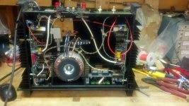
Nice job, Ken, neat and tidy, rather better than most rebuild jobs into older integrated amps.
Great that there is no smoke; that smoke MUST be kept inside all devices. Do have a good listen and report your findings here!
Cheers,
Hugh
Great that there is no smoke; that smoke MUST be kept inside all devices. Do have a good listen and report your findings here!
Cheers,
Hugh
Nice job, Ken, neat and tidy, rather better than most rebuild jobs into older integrated amps.
Great that there is no smoke; that smoke MUST be kept inside all devices. Do have a good listen and report your findings here!
Cheers,
Hugh
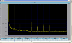
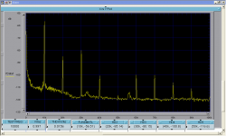
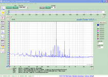
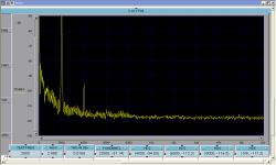
Thanks Hugh. I ran some more 10kHz spectrum test tonight these were at 6.6Vrms of both channels. The tests were'nt as good as the previously posted spectrum. The previous spectrum was running on a slightly lower voltage power supply but with 58,000uf caps and high order snubbing of the diode bridge. The setup of channel A (1st image) is is slightly different from channel B (2nd image). Channel A is as designed, Channel B is with a fixed 220 ohm resistor in lieu of trimmer P2. Otherwise their bias is set the same at 120mV across 0r32 total Re 0r10 Nchannel, 0r22 P channel.
Calculated THD 0.0149%
Listen begins tomorrow...
Ken
Attachments
Ken,
Don't put much stock in the THD; as a gross figure, it doesn't say much. What are significant are:
#1 ratio of H2 to H5 for 1W (higher the better, >25)
#2 percentage of THD attributable to H5 and beyond (should be beyond 98%).
Cheers,
Hugh
Don't put much stock in the THD; as a gross figure, it doesn't say much. What are significant are:
#1 ratio of H2 to H5 for 1W (higher the better, >25)
#2 percentage of THD attributable to H5 and beyond (should be beyond 98%).
Cheers,
Hugh
Ken,
Don't put much stock in the THD; as a gross figure, it doesn't say much. What are significant are:
#1 ratio of H2 to H5 for 1W (higher the better, >25)
#2 percentage of THD attributable to H5 and beyond (should be beyond 98%).
Cheers,
Hugh
So, is it morning there?
How do you calculate the ratio of H2 to H5? Just devide the one into the other in db values?
and #2, I can even begin to image the formula...
Ken
Almost 5pm here.... you are at 10pm, about 17 hours behind, no?
Yep, divide the two relative values into each other; ignore dB here. You can pick off the values from the simulation.
Those two metrics I have found are as close as it gets to predicting good sound.
Hugh
Yep, divide the two relative values into each other; ignore dB here. You can pick off the values from the simulation.
Those two metrics I have found are as close as it gets to predicting good sound.
Hugh
Divide is the same as subtract dB ratios.
If you have a 1mVac harmonic and it shows as -60dB on the plot and you also have a 250uVac harmonic which shows as -72dB then the ratio between them is either 250/1000 =0.25, or 60-72 =-12dB. Both give the same result, since 0.25 = -12dB
Now to that 98% of all distortion .
Extract the value of 2nd, 3rd & 4th harmonics as uVac or uVpk. Add them together.
Now divide that 2nd to 4th sum by the fundamental.
it should be most of the distortion result displayed on the results screen. Say you have 0.0205% distortion in amongst the fundamental.
Then 98% of that is 0.02009%
Did the 2nd to 4th sum contribute more than that or less than that?

Ken, if your measurement set-up is correct (I do not believe so) the amplifier performance is poor for the output is 1V (or 120 mW) into 8 ohms.
As Hugh pointed out, don't read too much in these figures, they are probably incorrect.
As Hugh pointed out, don't read too much in these figures, they are probably incorrect.
Ken, if your measurement set-up is correct (I do not believe so) the amplifier performance is poor for the output is 1V (or 120 mW) into 8 ohms.
As Hugh pointed out, don't read too much in these figures, they are probably incorrect.
Nico,
I'm trying to be critical of the amp, rather understand how Hugh characterizes a good sounding amp.
Regarding the measurement setup - the 1v you are refering to is the voltage out of the attenuator, the Vin was 6.6Vrms with an 8ohm load. I need the Vout to the spectrum analyzer to be 1Vrms so that it is referenced to 0db on the analyzer. This matters because I also put the signal through a Twin-T notch filter that gives a relatively arbitrary notch depth in the -40 to -70db range.
(As to why the image says 1 Volt, I have two places to connect the volt meter (HP8903A) on the attenuator one to monitor the Vin, second to monitor the Vout, I forgot to move it to the Vin position- regardless, it's position won't affect the spectrum)
Regarding the rule #2:
I calculated the %THD for 2,3 & 4H combined at 0.01490% and 5,6,7,8 & 9H at 0.00138%. The second value / first value = .093; 1 - .093 = 90.7%
Did I calculate this correctly?
Ken
Ken,
With the proviso that we should not read too much into these figures - they are steady state sine wave, after all, little relationship with music - there is an easier way.
THD (H2.........H20) - THD (H2,H3,H4) = THD (H5,H6,H7........H20).
The subtraction of the second term from the first will give you THD (H5, H6, H7........H20), which is, to me at least, a more indicative figure of how it will sound. If you take TJD (H2,H3,H4) and divide it by THD(H2......H20) the percentage should be greater than 98%. These are ball park, indicative only, but far more valid than THD alone.
Andrew's RMS derivation is NOT necessary if you have a simulator - and everyone has a simulator these days, no? - and his explanation that numerical division was equivalent to subtraction of indices left me in peels of laughter. Heck, I never knew that, did you?
Nico is 100% right. These figures are not very good. It could be that your analyser is measuring highish noise, and possibly distortion coming off the oscillator as well.
Cheers,
Hugh
Last edited:
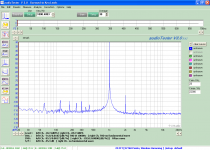
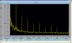
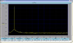
Maybe I wasn't very clear, the prior spectrum are at 10kHz and 6.6Vrms. Tonight I ran a few more spectrum, 1st at 1kz at 2.83Vrms (1watt) Krohn Hite source, 1kHz at 10Vrms using the computer and Juli@ sound card with the Knohn Hite as the source. I also ran 2kHz spectrum at similar power levels for comparison using the spectrum analyzer and KH source. You can see that the two are quite similar. Last plot is the Knohn Hite source at 1vrms out.
Ken
Ken
Attachments
Ken,
Looks better. These are quite respectable. I do not expect very low THD from this amp; loop gain is about 50dB and there is predominating H2. These are quite close to the simulator, within 5dB, impressive....
Thanks for sharing the plots,
Hugh
Looks better. These are quite respectable. I do not expect very low THD from this amp; loop gain is about 50dB and there is predominating H2. These are quite close to the simulator, within 5dB, impressive....
Thanks for sharing the plots,
Hugh
dear all,
do you have 80w 2sk1058 and 2sj162 based amplifier circuit.i have two transistor only and wand to use them.thanking you
do you have 80w 2sk1058 and 2sj162 based amplifier circuit.i have two transistor only and wand to use them.thanking you
- Status
- Not open for further replies.
- Home
- More Vendors...
- AKSA
- Swordfishy/ASPEN FETZILLA power amp