Member
Joined 2009
Paid Member
I'm back 
Business trips calming down, a bit more of my time back under my control.
Just read the last dozen pages, boy it's a busy thread. A busy thread is a good sign. Better to see some 'lively' discussion than apathy.
However, if I go back to the first post I read "Gareth Ingram (aka Bigun) of Ontario will be directing this thread" and based on where things are I think Hugh should fire me
Actually, I like this committee approach. It's better.
So where are we - it's headed to a SE design. Is it the original schematic modified or did we go all the way to CFP or something ?
Cheers,
Hugh
Aww, you guys are too much like tut-tutting old women!
I'm outta here!
I'm outta here!
An externally hosted image should be here but it was not working when we last tested it.
Member
Joined 2009
Paid Member
Aww, you guys are too much like tut-tutting old women!
I'm outta here!
An externally hosted image should be here but it was not working when we last tested it.
Can't stand the heat ?
Love the bike...looks way more fun than amplifiers !
I see nothing wrong in microengineering an audio amp.
It is better to be above reproach then below... As long as we're improving the design, why not let it get better? "I couldn't hear the difference" is a poor excuse for coming up with an inferior design (no offense). This is an AKSA project, anyways. Aren't we aiming for excellence beyond reproach?
- keantoken
Hey John,
If you are very lucky, as your testosterone levels drop, you too will become an old woman!! The alternative, if you think about it, is unthinkable!
Never did understand Hardly Movingsons, not enough power, not even for a feisty old woman.....
Gareth,
You've been re-hired!
Kean,
The idea is to do something which really does sound good. This means, in the absence of anything better to measure by, we go for a single ended design, with all its distorting implications. All my experience of amps leads to this conclusion, and particularly with the intimacy and critical musicality of headphone amps where second best is really not acceptable. We don't need big power, so can accept the limitations of Class A, though a formal heatsink might be needed. The amp is very simple at present, I do have other designs, but I want to keep it simple. Nico's point about cap coupling is probably on the money, as a CFP does have wildly drifting offset control. But there are other options, too, such as a rush with se cfp output into a CCS.
Cheers,
Hugh
PS: My choice, something better...
Attachments
Unfortunately I'm sort of out of place in this thread since I've only listened to what, 3 or 4 crappy stereos in my life, each slightly better than the one before. All of them through the worst speakers imaginable.
So while I can offer some technical knowledge, I'm not so good at the musicality and sound.
- keantoken
So while I can offer some technical knowledge, I'm not so good at the musicality and sound.
- keantoken
Unfortunately I'm sort of out of place in this thread since I've only listened to what, 3 or 4 crappy stereos in my life, each slightly better than the one before. All of them through the worst speakers imaginable.
So while I can offer some technical knowledge, I'm not so good at the musicality and sound.
- keantoken
All you have to do is listen
Member
Joined 2009
Paid Member
SE and CFP sounds great. My current DIY amp project is also SE and CFP so now I only have to think about a consistent set of challenges.
The rush front end sounds good too. CFP is not new, but the combination with Rush would be a road less travelled. And KT, you've already championed this structure in another thread with some passion - which in my view bodes well for it's use.
I could be mistaken, but did we drop the line-out connections along the way ? - I hope not, the SE Rush-CFP could make a unique pre-amp option.
With a CCS load on the CFP we have the possibility to keep this simple and I like the implication that there would be a constant current draw on the power supply and I think this would a good thing for overall performance.
I am not at all afraid of an output capacitor, don't have to worry about dc drift or hurting somebody's expensive earphones.
How important is the CCS load for the 'sound' - would the use of a MOSFET be worth considering here so that we can stop worrying about SOA and temperature dependence ?
On another topic, I saw some nice drawings for the front panel. I do like the more symmetric layout with the large control placed in the centre. And I agree 100% with KT, the power switch should go where a drunk listener can find it - perhaps the chasis could be designed to support a pint ?
p.s. I like the Harley... it's the bike that gets the girl.
Question about constant output current
Thinking about the single ended amp it struck me that if we kept the current through the output transistor constant then it would potentially reduce the distortion. Modelling the circuit (32 ohm load 45ma peak current through it) with an extra current sink which sinks an inverted version of the current through the load in parallel with the CCS reduced the 2nd harmonic from -65 to -80dB and the third from -65 to -106dB in my simulator. These are reasonably large reductions if they could be achieved in practice.
I don't know much about amplifier design (although I have learnt quite a bit from this thread) so my question is are there common circuits that keep the current through the output transistor constant or does the whole idea fall down in practice (simulations cancelling 80% of the current variation in the output transistor gave 2nd and 3rd harmonics of -71 and -98dB respectively so the cancellation needs to be fairly accurate the reap significant rewards).
My sketchy (and possibly flawed) idea for an implementation would be to use a small resistor between the +ve supply and the emitter of the output transistor to monitor the current through it and to somehow regulate the current sink to keep voltage across this resistor constant. If the voltage drop is constant it should not affect the operation of the cfp if the value of the collector resistor of the input transistor is adjusted slightly.
Nico - its great to see you back, I have learnt a lot from your posts
Best wishes
Phil
Phil,
In practice, the ear is not sensitive to even order harmonics to H6 below about -60dB, but hypersensitive to odd order, H5 on, at very low levels. Varying current through the output transistor will produce asymmetric, even order distortion, and need not be eliminated since all levels are well under -60dB. If we used a complementary CCS to compensate the ebb and flow of the SE output stage and yielding equal current through the output transistor, it would certainly reduce even order distortion but do little for odd order, which might even increase.
As even order distortion can mask odd order, it's best to leave well alone. What is of concern is the current amplification; most front ends only pass a couple of mA or so, yet the output stage will be required to sink at least 130mA in order to drive low Z headphones. The VAS should operate into a relatively high Z to give good loop gain, so this means that a buffer - in this case effectively a CFP - should be used to amplify the current gain of the second stage, the VAS, so it easily interfaces with the output stage.
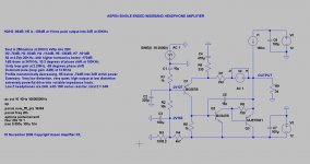
We are aiming for a monotonically decreasing distortion spectrum, that is, H2-H3-H4-H5 etc all decreasing successively by at least 12-15dB on a log frequency scale. This is favoured by such designers as Jean Hiraga. I'm presently modelling a circuit which gives H2 -78dB, H3 -93dB, H4 -114dB, H5 -130dB, H7 -161dB, all into 34R at 20KHz 0dB. If the circuit is very fast, (and I can get the dominant pole to 13.5KHz, normally around 2KHz), then intermodulation should be minimal, and with unity loop gain at 2.5MHz and around 75 degrees of phase margin, this amp should be unconditionally stable and very clean, with a benign distortion profile of exceptional low magnitude.
The beat goes on......
Hugh
In practice, the ear is not sensitive to even order harmonics to H6 below about -60dB, but hypersensitive to odd order, H5 on, at very low levels. Varying current through the output transistor will produce asymmetric, even order distortion, and need not be eliminated since all levels are well under -60dB. If we used a complementary CCS to compensate the ebb and flow of the SE output stage and yielding equal current through the output transistor, it would certainly reduce even order distortion but do little for odd order, which might even increase.
As even order distortion can mask odd order, it's best to leave well alone. What is of concern is the current amplification; most front ends only pass a couple of mA or so, yet the output stage will be required to sink at least 130mA in order to drive low Z headphones. The VAS should operate into a relatively high Z to give good loop gain, so this means that a buffer - in this case effectively a CFP - should be used to amplify the current gain of the second stage, the VAS, so it easily interfaces with the output stage.
We are aiming for a monotonically decreasing distortion spectrum, that is, H2-H3-H4-H5 etc all decreasing successively by at least 12-15dB on a log frequency scale. This is favoured by such designers as Jean Hiraga. I'm presently modelling a circuit which gives H2 -78dB, H3 -93dB, H4 -114dB, H5 -130dB, H7 -161dB, all into 34R at 20KHz 0dB. If the circuit is very fast, (and I can get the dominant pole to 13.5KHz, normally around 2KHz), then intermodulation should be minimal, and with unity loop gain at 2.5MHz and around 75 degrees of phase margin, this amp should be unconditionally stable and very clean, with a benign distortion profile of exceptional low magnitude.
The beat goes on......
Hugh
How important is the CCS load for the 'sound' - would the use of a MOSFET be worth considering here so that we can stop worrying about SOA and temperature dependence ?
A MOSFET CCS would be nice but it will lose BW at HF over a BJT. I don't know how that matters or affects the sound.
The Rush (or NTP) CFP will work well but it's more complex, more expensive, more prone to skepticism and dogma, and it will have any shortcomings that come with conventional NFB.
It will have lower distortion, greater Vbe offset (though I know how to fix that). It won't have as perfect a distortion spectrum as the SE variant (though not much different).
I think the SE variant is good enough, and going to the Rush-CFP might be pulling teeth - what we have is quite good with minimal chance of error, and the increased complexity of the Rush-CFP will, I believe, increase all non-harmonic distortions.
(just for the record, I AM very knowledgeable about the Rush-CFP.
)- keantoken
Okay, regarding the MOSFET CCS idea, I just had a simulation and noted the following:
1: Output swing is reduced by about 4V.
2: CCS linearity is much improved over simple 2 transistor CCS. It would take some modification to get this performance out of a BJT CCS due to Ib and Early affect.
3: Distortion added by the BJT CCS is purely monotonic.
4: Virtually no distortion is added by the MOSFET.
I suggest we use the MOSFET CCS, if there is nothing wrong with the restricted output swing and BW.
Phil:
Your input is valued and I ask that you don't refrain from posting your suggestions and thoughts if you have any.
- keantoken
Last edited:
Member
Joined 2009
Paid Member
Member
Joined 2009
Paid Member
Hugh has chosen the components for easy availability; the only difficulty maybe Q3, the MJE15031, chosen for moderate speed, excellent gain linearity and thermal robustness. As a buffer (CFP in an emitter follower config) it could be implemented using a number of devices e.g. BF470 and 2SA1837. However, running at 1.56 watts it needs to be up to the task and installed with a good heatskink.
Q1 and Q2 can be chosen from a range of available low voltage parts that most of us are already familiar with. Q1 is used as the input device; as a single device it doesn't need to matched (as with an LTP) and since there is only one Vbe junction involved we anticipate greater linearity. It's driving an easy load at low voltage so very little current variation.
Q2 is biassed into a good linear operating range (4mA).
CCS should be a simple, MJE15030 with a red LED voltage reference. This should be used with a low ripple smps of 24V 1A continuous rating.
There's more to say, but let's digest this for now...
Q2 maybe should be given more attention as a VAS; should we use Hugh's pick, the 2SC3423?
Regarding Gareth's MJE15031 CCS... This CCS is highly nonlinear at these currents. I suggest to use the 2-transistor type CCS at least, and a MOSFET would be better instead of the 15031.
- keantoken
Regarding Gareth's MJE15031 CCS... This CCS is highly nonlinear at these currents. I suggest to use the 2-transistor type CCS at least, and a MOSFET would be better instead of the 15031.
- keantoken
Member
Joined 2009
Paid Member
Regarding Gareth's MJE15031 CCS... This CCS is highly nonlinear at these currents. I suggest to use the 2-transistor type CCS at least, and a MOSFET would be better instead of the 15031.
- keantoken
I do like the idea of a MOSFET for a CCS because you don't have to worry about the gate capacitance (once it's charged that is) and it draws very little gate current. A BJT CCS has this high level of base current to supply which is why a 2nd transistor can be of help. However, I don't think the current levels here are so high to worry about needing two devices.
Linearity - not sure if this is significant enough to worry about, the nfb should take care of this unless you think there's enough non-linearity to mess up the FFT ?
- Home
- More Vendors...
- AKSA
- Aspen Headphone Amp