Member
Joined 2009
Paid Member
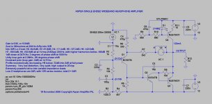
Consider the distortion levels, Kean, they are VERY low and the non-linearities in the CCS will have little effect on the audio signal for two reasons; output is controlled by the buffer EMITTER, which is in turn set by the VAS, and the negative feedback is very powerful as we have such high OLG. A mosfet is cool, sure, but it takes about four volts off the output, limiting us to 16Vpp with clip first appearing on the positive rail. With a bipolar, we can get around 20Vpp. This added headroom is good use of available resources. A 90dB/mW headphone of 2K impedance needs 18Vpp to achieve around 99dBA, which is loud, but we all know some like it HOT.
Hugh
Hugh
Last edited:
Hello Hugh and guy's
I've just seen my email and reply to it.
As I reply in my email it's a very good circuit Hugh, low distortion, stable, and it should sound like an SE amp with better resolution than the previous SE circuit.
All-right, I vote yes for this one.
Ok for a CCS.
Thank
Bye
Gaetan
I've just seen my email and reply to it.
As I reply in my email it's a very good circuit Hugh, low distortion, stable, and it should sound like an SE amp with better resolution than the previous SE circuit.
All-right, I vote yes for this one.
Ok for a CCS.
Thank
Bye
Gaetan
Last edited:
Member
Joined 2009
Paid Member
I just simulated it, you are correct.
- keantoken
Wow, I can't even get my computer started as fast as you can complete a sim!
Hello Hugh and guy's
Thank
Bye
Gaetan
Boy, you're in and out fast! 🙂
- keantoken
Wow, I can't even get my computer started as fast as you can complete a sim!
It gets better with practice. 😉
I should know considering I've been doing all the specialized simulation here...
- keantoken
It gets better with practice. 😉
I should know considering I've been doing all the specialized simulation here...
- keantoken
Hello keantoken
You are the Lucky Luke of the simulation... you sim faster than your shadow 😉
Bye
Gaetan
Member
Joined 2009
Paid Member
It gets better with practice. 😉
I should know considering I've been doing all the specialized simulation here...
- keantoken
You've certainly made more contributions that I have managed. Still, it seems we have a 'team' that comprises of lots of very useful skills for the project.
Have you considered if it's worth the trouble extending the simulation to include a small passive model of the headphone rather than a simple 'pure resistor' ?
I'm like the backup-guy who simulates when things get sticky. 🙂
I'm certainly not alone here in simulations, though I make an effort to show the differences that usually aren't simulated for whatever reason. I make it a point, if it comes down to guessing and speculating, to simulate instead of guesstimate. I've made some contributions, but I'm limited in that anything I say can't be definitive; I haven't built more than 10 real circuits in my life.
In short, I talk a lot, but don't have anything to show for it.
As for a reactive load simulation, I don't know how necessary it is and I heard it said that headphones are much less reactive than loudspeakers. I think the largest issue where this is concerned is with an AB amp, where it might cross over into B during low load impedances; but this isn't a problem with the current class A design.
- keantoken
Last edited:
a single ended ClassA amp will go into current clip. It cannot supply more than what the CCS is set to.with an AB amp, where it might cross over into B during low load impedances; but this isn't a problem with the current class A design.
Can somebody pls explain the value of R3 in the latest SE schematic for me? Is it a pot to adjust the offset, or what does the value "1020.3" mean?
(Well, I might have missed a few posts already...)
I appreciate very much this discussions&develepments @this thread - thank you.
(Well, I might have missed a few posts already...)
I appreciate very much this discussions&develepments @this thread - thank you.
BTW, for an easy double blind listening test for audio files another add-on for the very versatile foobar player can be useful, the so called "ABX comparator". It is activated by the context menu /utils/ABX two tracks.
Hi Lohk,
Nice to see you here!!
This is the precise value of resistor needed to achieve zero offset. In practice, it would simply be a 4K7 resistor supplying a blue LED, around 2.5V, with a 1K pot across it. The wiper would supply the bias voltage, suitably decoupled with a cap.
There is, of course, no readily available resistor of that size! However, even there were, the bias would still vary with applied voltage, so it's adviseable to have a voltage source in that position. An LED is useful, of course, as it gives a visual indication of operation.
Hugh
I assume the one earth connection at the input is something used in a sim? Bleeder resistor missing? Hard to generate a signal when it's shorted.
Is the virtual earth supply still contemplated?
Sheldon
Is the virtual earth supply still contemplated?
Sheldon
Last edited:
Anyone thought of using a simple three terminal voltage regulator as CCS, low component count and good noise rejection. And temperature stable.
Thanks, Hugh.
As a proud owner of a new AKG K702 I am looking for a better amp anyway.
I do not know the price of these headphones overseas but here it is less than 400EUR, they are pretty unbeatable for that price.
As a proud owner of a new AKG K702 I am looking for a better amp anyway.
I do not know the price of these headphones overseas but here it is less than 400EUR, they are pretty unbeatable for that price.
I assume the one earth connection at the input is something used in a sim? Bleeder resistor missing? Hard to generate a signal when it's shorted.
Yes, for the purpose of assessing loop gain you need to short out the input signal.
Is the virtual earth supply still contemplated?
But of course!
Hugh
Nico, I prefer to use the MJE15031 with a led. Simple, and better bandwidth. Besides, current regulation is not too important here; you could replace the CCS with a resistor, as you did with the earlier SE CFP, and not see much quality degradation.
Hugh
Hugh
- Home
- More Vendors...
- AKSA
- Aspen Headphone Amp