carpenter said:My air-core choke was beginning to melt it plastic bobbin--cheap plastic!😀 Couldn't be the heat?!?
carpenter said:flg--several post back, you mentioned that 147K ll 442K / R2 gives the gain. If this is so, then I should replace R2 (the 221 ohm resister) with something on the order of 10K? That would give a gain of 11; assuming I understood your formula correctly.
I remember
The measured supply was 28.5V
and 23V on the lower side of the choke
Means voltage drop in the choke is 5.5V
You have 3A bias of class A
So, 5.5x3=17W heat contuously per choke
flg is on the bed
and the gain formula is correct
if we assume the gate as a virtual ground
Yes, it is, as Papa says
By the way
we are all old freaks, having young minds
We often forget and forgot . . . 😀

Thanks, babowana.🙂
Long live the old freaks!


And when you figure that the choke has both windings on the same bobbin, that's 34 watts.
Long live the old freaks!
And when you figure that the choke has both windings on the same bobbin, that's 34 watts.
So, suplimenting the home heating with the ZV7??? 
Yes, R2 might be better as a 10-20k. What is the gain your getting now? I guess it probably changed with your new inductor??? If you put in 1V what comes out? And just to be confusing, is that 1V in Differential? and the output??? (1V might actually be to much maybe try.1V first) So far, I had only been thinking of one side of the amp 🙂
I was wandering though, if you are running open loop, what is the OL Gain??? When you start getting control with feedback you will have an idea how much by subtracting OL gain - closed loop gain...
When running the o'scope on one side of the differential, I measured 200 mV out of a buffer, and almost one volt out of the power fet. That's with the old air-core inductor.
One volt in would drive the output fet into major clip mode.
On another topic. Malvino's book falls short in the FET enhancement mode. I can't discern the "k" factor that his formulas ask for because some of the pertinent data is missing from the mfgs. data sheet. He needed to offer alternate formula's or techniques to arrive at the "k" factor. I.e., in particular, the VGS-on and ID-on data. Neither transistor mfg. offers this information. Perhaps it can be gleaned from the performance charts, but Malvino doesn't describe how.
John🙂
carpenter said:When running the o'scope on one side of the differential, I measured 200 mV out of a buffer, and almost one volt out of the power fet. That's with the old air-core inductor.
One volt in would drive the output fet into major clip mode.
John🙂
Not what I would have expected😕 😕 😕 Sounds like a gain of 4😕 Hmmm
So, I decided to throw a quick circuit together in the simulator, that looks like your ZV7-T... Not exactly, but easy. And the gain is about 4???

I need to play a little more...
I need to play a little more...
flg, I think you're a gem. Thanks for helping me make my amp sparkle.🙂
The buffer is a source follower with a gain of less than one? Maybe that's it.
The buffer is a source follower with a gain of less than one? Maybe that's it.
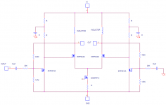
Well John, I had this Idea... while looking into the gain thing with your amp As ussuall, I don't know how to get a "Schematics" file into a ussuall format for this stuff or I'ld give you a pic. But here goes. You don't need C2 R3 and RP1 at all. You need an adjustment though, so you probably want an RP1 where R6 is...
My circuit doesn't appear to be optimized yet but my only big difference is 20K input resistors(R2s)😀 😀 😀
As ussuall, I don't know how to get a "Schematics" file into a ussuall format for this stuff or I'ld give you a pic. But here goes. You don't need C2 R3 and RP1 at all. You need an adjustment though, so you probably want an RP1 where R6 is... My circuit doesn't appear to be optimized yet but my only big difference is 20K input resistors(R2s)😀 😀 😀
Hey flg,
On page 844 of Malvino's text, he mentions that the formula for closed-loop gain is:
ACL = R1/R2 + 1
I tried it out; I divided 442K by 147K and added 1. Guess what?
John🙂
btw, R3 and P1 adjust the bias of the gain fet. How would you make that adjustment without this resistor circuit?
On page 844 of Malvino's text, he mentions that the formula for closed-loop gain is:
ACL = R1/R2 + 1
I tried it out; I divided 442K by 147K and added 1. Guess what?
John🙂
btw, R3 and P1 adjust the bias of the gain fet. How would you make that adjustment without this resistor circuit?
Well, Regarding Malvino's formula. That is probably right but, he was refering to your R4 and R2😀 And, he probably did not have R6 in there dumping some of your feedback😕 😕 😕 I'll have to think about it a little...
Regarding biasing the output FETs... I think you want about 4 Volts on your current source (Q3). That means you need about 4 more Volts (Vgsth of Q1 + Q2) on the gate of Q1 + Q2. So, if the Buffer Threshold is about 3.5 Volts: (4+4)-3.5 = 5.5 Volts at the buffer gate. If your output (absolute value, not differential) was at 23 Volts, then the R4 and R6 voltage divider function should be set up for 5.5 Volts on the Buffer Gate. Then, you would probably want a pot to help you tweak offset in the R6 location 😀 😀 😀
I'm not sure how out in space all that sounds but I think N.P. is due for a comment or two pretty soon. It looks good to me😎
To my beginner's brain, you've got some really good ideas going there, flg. As it stands, the buffer is delivering nearly 10 volts at the source pin--just about what I'm running at the gate of the power fet. The feedback resistors are drawing from the same location for both buffer and power fets.
Cool.
I could replace R6 with a pot for dc offset adjustment.
I'll play with this concept on my next amp; which I intend to start any day.
Thank-you very much.🙂
Cool.
I could replace R6 with a pot for dc offset adjustment.
I'll play with this concept on my next amp; which I intend to start any day.
Thank-you very much.🙂
I don't know what to say dude, That's a regulater???,,, Bobowana, N.P., where are you when I need you Guy's??? N.P. Help us out will Ya???
O.K. John, I left out the "gate stopers"(221 ohm gate resistors) But give me some more problems to think about 😕 😕 😕 I think I said that was close and easy. That meant I actually used 8 ohm loads, not Inductors, and 40Volt V+, cause that's me... I think your circuit is worth changing to my idea??? Anyone else have a comment??? I said I didn't optimize it, but, I'm pretty good first try ussually... I also think I said I wanted some time to think(optimize on the sim first)😀
Sorry bud, I got the parrental units and the rest of the family to think about right now. I gave you a circuit "variation" on the Holiday weekend close enough to help you out and if you blow **** up, I'll send you replacements, I just want your Holiday to be cool too. I have IRFP044N's and ZVP3310As, Do me a favor and try my changes unless someone else jumps in and say's don't...
Just that it's stressfull enough here right now and the sim said cool data... A gain of 9 or 10. And a 1watt distortion of .0 something. Im listening to my new RUSH CD 😀 😀 😀 Later
Happy Holiday's... What are the rest of ya doin???
John, my schez did not show an Iq for the buffer but if you have 10 Volts on it you shou'ld go look at the data sheet and stay at most 1/3rd the Pd... My sim had about 15mA and almost 9 Volts... No Brain 😀 ... 1/3rd is a good no Brain Pd...
Thanks, flg.
I have dozens of 3310s and a hundred 044Ns and at least 75 240s, so I'm in great shape in the transistor dept. Thanks for offering to help me out. I bought that many knowing that seat-of-the-pants newbie plug-and-play would fry a few.
I like your ideas and will plug them in on my next amp which I'll be starting very soon. I've got this one running well, so I don't want to mess with it any more. This way, I have something to compare the new amp to.
Please don't stress out over my stuff😉 😀 , I'm happy as a clam. Your efforts to educate me are just wonderful.
Good luck with your parents, I'm sorry to read of your father's condition. I certainly empathize, what with my recent heart-attack. At least for me, my health is returning rapidly, and here on this forum with your fine fellows, I'm very happy while convalescing.
Love ya bud,
John🙂
btw, Malvino's regulator was only to show how I though gain was supposed to be figured in my current amp, beings I use a similar resistor circuit to bias the buffer. I could be all wet, and this is why I posted it. You guys can show me the proper technique.
I think . . .
Easy to calculate the voltage gain
of Malvono's feedback voltage regulator
because there is an apparent voltage
reference, i.e. (Vz+Vbe)
ZV7-T however has a complicated
feedback loops composed of
R2, R4, R6, R3 and P1
My brain is too small 🙂
Easy to calculate the voltage gain
of Malvono's feedback voltage regulator
because there is an apparent voltage
reference, i.e. (Vz+Vbe)
ZV7-T however has a complicated
feedback loops composed of
R2, R4, R6, R3 and P1
My brain is too small 🙂
- Status
- Not open for further replies.
- Home
- Amplifiers
- Pass Labs
- ZV7-T (transformer)