Well, it's 3:45 in the morning and I'm so stimulated that I can't sleep.
I wanted to thank you babowana for your input. Laying there in my bed I mulled over your posts and it finally sunk in. Wow.
I can see where my amp is dependent on the 100K resistors in my X-over and how they have become part of the input circuit. I had to go over that layout in my mind repeatedly. Eventually, it took hold.
Reading my electronics book, I found information that describes how I can replace R13 with a potentiometer and adjust the gain that way. Now I'm really getting excited!😀
Thanks for being patient with me,
John🙂
carpenter said:Well, it's 3:45 in the morning
Crazy . . . ?
These days I try to do all stop at 10pm
Bring wine glass, listening to jazz music and watching ESPN
Go to bed 11:30pm
It takes one hour to fall into darkness
We are welcomed to the club
We are the same diyers 😀
Cheers,
I stayed up too late last night, so I mainly listen to music today. I managed to rotate various resistor values in and out on R2 and recorded "source" voltage measurements. At the moment I'm listening to the amp with 10K resistors. The gain is good. I'm looking forward to replacing R13 with a potentiometer and controlling gain there as well.
I can't thank babowana enough for sharing his thoughts with me; what a wonderful person--so patient, too. Tomorrow, I will use his ideas to explore isolating the input of my buffer section from the electronic x-over. This way I can run various resistor values to ground at the buffer gate. More data to record. Cool.
The buffer that Nelson offered us does an extremely good job of delivering micro-detail. I've never heard anything like it. A little bit of the weight is missing, but I'll keep puttering around to see if I can get it back. For the moment, I wouldn't trade this little fellow for the world.
A friend of mine came over today and listen to music with me for an hour. He said that he'd listened to a $90,000 system several weeks back and that my system offered similar performance. 😀
I grinned and thanked him for blowing smoke up my you-know-what. He put his hand on my shoulder and said it was no exaggeration. God bless friends like that. (BS or not).🙂
Love you guys,
John🙂
carpenter said:I can't thank babowana enough
John🙂
Don't mention it, please!
I just love sharing together with, as others do.
Anyhow, thank you very much for the nice words.
🙂
carpenter said:A friend of mine came over today and listen to music with me for an hour. He said that he'd listened to a $90,000 system several weeks back and that my system offered similar performance. 😀
John🙂
Wow! Great!
I could imagine . . .
Actually I have a plan to build one. Don't know when, tho . . .
I will use your circuit
🙂
Hi,
I couldn't wait until tomorrow...
So, just now, I utilized babowana's idea--it works like a charm.
I used a couple of nice 1 uF film caps on the input. Then I added 442k resistance to ground at the buffer gates (R4 was already 442K). I reduced R2 to 221 ohms. I also reduced R13 to 1K.
The buffer source voltage is now 15.7 volts. This is almost midway between ground and positive supply.
The results are wonderful. That missing body of midrange sound is back. The micro-detail is slightly less, but still present. It's probably harder to pick out because the mids are stronger.
I'll rewrite the schematic and post it at a later date.
John🙂

Now we could have good advantages, IMHO.
As far as I understand, P-ch ZVP and N-ch IRF have opposite
characters of Vgs-vs-Id curves, which co-operate to
cancel distorsion to certain degrees.
As you know
If we reduce R6, the Vds goes down, and vice versa.
If we reduce R13, the buffer biasing current inceases, and vice versa.
Using the Vgs-vs-Id curves or using our trained ears,
and by adjusting R6, or R13 or both, we could find out
the most beautiful result, I think . . .
Cheers,

Using the Vgs-vs-Id curves or using our trained ears,
and by adjusting R6, or R13 or both, we could find out
the most beautiful result, I think . . .
I think you are correct. I plan to install two-ganged potentiometers (audio chassis style with knobs) in these two locations so I can do just that. I may utilize a four-gang pot to include R4 alongside R6. This way I can adjust feedback to taste. Or, maybe I should use three two-gang pots to adjust all three variable independently. The sound can be varied to a large degree.
For the moment, this amplifier is an amazing example of following one's bliss.
I'm extremely pleased with the sound. I like it better than Zen 1, better than the AX (I've built both). It sounds warm, never grainy. But, then again, I play it through my horns and don't have to use more than two or three watts max. The distortion level at this volume is minimal.
Thanks again for your excellent suggestions, babowana.
John🙂
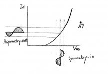
In my continuing attempts to optimize my ZV7-T, I've made adjustments to the gate voltage. I used this chart as my guide.
As configured in the previous schematic, the gate voltage comes in around 12v. This is too high according to the graph I'm presenting.
I managed to lower the gate voltage by reconfiguring R13 to 1.5K and R6 to 147K. This netted me 6 volts at the gate and 9.5 volts at the source; it's interesting that the source voltage always remained exactly 3.5 volts above the gate voltage in my reconfiguration attempts. 🙂
How does it sound: just perfect--until the next reconfiguration makes it better. Diana Krall's band really impresses me, as does Diana. I can hear sounds that have never, and I mean HAVE NEVER come out of that CD. It's the coolest thing...
Edit: R6 in the previous schematic really should be converted to trim pots. This way the outputs can be adjusted to be perfectly symmetrical. I'm almost of the mind that the sources can be linked and given a constant current source at the junction.
Attachments
In this illustration, I'm left feeling confused--what else is new😀 --as it seems that I'm supposed to subtract the VGSth voltage from the actual gate voltage. If this is the case, then I'm left if far better shape with regards to the load-line I posted previously. Instead of having a VGS of 6 volts, I'm closer to 3, or so. This places me somewhere around mid-center of my load-line. I think...
Help?
John🙂
Help?
John🙂
Attachments
carpenter said:Help?
Don't expect . . .
The crowds show no interest in this kind of things
Do you need a good specification for customers?
You are an end-user, aren't you
Just trust my music and my own taste
Or buy a distorsion analyser as Papa recommends
I'm going to buy one
Have difficulty in finding a proper one for me
because I have never experienced with such equipment
hmm . . .
If you really want to play with the curves
I think you should consider Id-vs-Vgs curves
But remember that very often I'm wrong 😀
Good luck 🙂
Attachments
Carpenter, Yes, your voltage gate to source on your 3310 is always going to be about 3.5 or so. In the original ZV4 buffer, the Drain was at ground and the gate effectively was too. Since you have a voltage at your output (23V I think, ZV4 had 0 Volts at the output) you need an R to ground at the gate and your feedback loop also acts as a voltage divider. Some of that divided voltage will pull up your gate. There will still be 3.5 Volts from gate to source though. And that gate voltage will be applied to the output of whatever you drive this thing with so you need the input cap on there. The input signal will also see the gate to gnd resistor and possibly loose some input level. All of this needs to be taken into account for proper operating point of the follower and the overall gain set-up.
It's time for me to break out my analysis stuff for my L Loaded ZV9. I have a Creative E-MU 1212m sound card in my putor and RightMark Audio Analysys software and True RTA software. I got them running a while back but then ended up having a computor problem... Time to get it running again...
Check out some of this software, if you have a good sound card, some of it is free
Thanks, guys.🙂 We're in the middle of intermittent power outages, so I'll be brief:
My wonderful book, the one that cost me a $1.42 arrived today and I'm all over it like ugly on an ape. It has quite a bit of info on load lines and how to locate the proper Q point. It also give some down-and-dirty tricks on getting the signal balanced so each transistor clips evenly.
Oh boy,
John😀
My wonderful book, the one that cost me a $1.42 arrived today and I'm all over it like ugly on an ape. It has quite a bit of info on load lines and how to locate the proper Q point. It also give some down-and-dirty tricks on getting the signal balanced so each transistor clips evenly.
Oh boy,
John😀
We danced like renewed lovers. She kept me up most of the night, last night. Oh the secrets we shared--actually, I mostly listened while scratching my head.😀
I owe Bryan; he mentioned the book in an earlier post.
What the heck, I owe most of you guys
Ahhhhh, load lines...
John🙂
I owe Bryan; he mentioned the book in an earlier post.
What the heck, I owe most of you guys
Ahhhhh, load lines...
John🙂
You're not going to believe this:
I put the 5pF C12/C12a caps in the loop--yes, I've been running the amp without these caps up to this point ever since a soldering iron mishap and the amp sounds somewhat glaring--if not harsh with them. I removed the little fellows and the sound became pleasant once more.
Another thing. I discovered that when this amp is run in balanced mode it doesn't sound nearly as warm and sweet and when run single ended. This observation came about as a result of my placing my Aphex single-ended/balanced converters on the scope. The original unit (model #228) that I was using at the inception of this project runs single ended out, although it looks to be balanced due to the xlr output. Sure fooled me. They must ground out pin 3 internally.
I substituted a fully balanced Aphex unit in it's place. The sound is very sharp and clear, but lacks warmth. I must like the sound of second-harmonic distortion.
In conclusion: no caps for C12/C12a and go with single ended inputs if you prefer a warmer sound. That's not to say the warmer sound isn't clean sounding, it has plenty of detail. It's just so smooth--the high frequencies don't jar the nerves.
John🙂
babowana, I just opened the little graphic your sent on post 233. Nice piece of info on a load line. Is that the transfer characteristics curve? Please explain how you did that. 😀
I put the 5pF C12/C12a caps in the loop--yes, I've been running the amp without these caps up to this point ever since a soldering iron mishap
and the amp sounds somewhat glaring--if not harsh with them. I removed the little fellows and the sound became pleasant once more.Another thing. I discovered that when this amp is run in balanced mode it doesn't sound nearly as warm and sweet and when run single ended. This observation came about as a result of my placing my Aphex single-ended/balanced converters on the scope. The original unit (model #228) that I was using at the inception of this project runs single ended out, although it looks to be balanced due to the xlr output. Sure fooled me. They must ground out pin 3 internally.
I substituted a fully balanced Aphex unit in it's place. The sound is very sharp and clear, but lacks warmth. I must like the sound of second-harmonic distortion.
In conclusion: no caps for C12/C12a and go with single ended inputs if you prefer a warmer sound. That's not to say the warmer sound isn't clean sounding, it has plenty of detail. It's just so smooth--the high frequencies don't jar the nerves.
John🙂
babowana, I just opened the little graphic your sent on post 233. Nice piece of info on a load line. Is that the transfer characteristics curve? Please explain how you did that. 😀
carpenter said:babowana, I just opened the little graphic your sent on post 233. Nice piece of info on a load line. Is that the transfer characteristics curve? Please explain how you did that. 😀
Hi, John
The curve was an outcome of my non-distilled work. Means that it is not on the actual scale. Anyhow, I think that it is good enough to represent the characteristic of MOSFETs. As you know, the transconductance is non-linear, which is the cause of distortion.
The correct curves could be obtained from the datasheets, hopefully . . . 😀
I keep coming up with impossible data to place a Q point on the I/V sheet for the little buffer FET--maybe, because of the way it's being utilized. I can get a load line going, but the gate voltage and the drain voltage are joined at the hip, so to speak; they're always roughly 3.5 volts apart. I.e., I'm currently running 5.75 volts Vg and 9.25 volts Vd. If I set a Q point at 9.25 volts on the graph's horizontal scale, the other factor, 6 volts, is nowhere near the load line; it should be closer to 3 volts.
Still, it's fun stuff,
John🙂
Still, it's fun stuff,
John🙂
- Status
- Not open for further replies.
- Home
- Amplifiers
- Pass Labs
- ZV7-T (transformer)