carpenter said:The horn made the most beautiful hiss I've ever heard.
I really hate any hiss from girl, wife and speaker . . .
Doesn't matter beautiful or ugly
😀
carpenter said:warm, single-ended sound. Soft and pretty.
Hiss - warm, single-ended sound, soft and pretty
Mmmmmmmmmmmmm . . .
You know what I'm thinking about . . . ?
😀
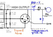
I assume the measured V is after connection of the elec x-over.
I.e. x-over provides about 100k, one end of which is connected to R2 and the other end running to the ground.
I'm intersted in, giving you this Q. Tks, 🙂
I.e. x-over provides about 100k, one end of which is connected to R2 and the other end running to the ground.
I'm intersted in, giving you this Q. Tks, 🙂
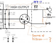
If you disconnet the x-over and re-measure V
you will read 23V at the gate of buffer
Now I understand that your ZV7-T is tailor-made
only for the connection to the x-over
And that is the reason why the hiss happens
when the R is added to the ground
I think that attaching both the input coupling cap
and the R to the gnd will cure the hiss and make the
amp free to receive all input sources whatever they are
Take few more cheap and easy tests
Enjoy! 🙂
quote: Originally posted by flg
I believe in ZV8 & 9, Nelson uses a gate to GND R in the circuits without feedback. Then when he adds feedback he takes them out...
response from Nelson Pass:
They are still there because the output is attached to ground
via resistance, and so a ground reference is still there through
the feedback resistor
How do you intrepret this, babowana?
Attachments
carpenter said:How do you intrepret this, babowana?
Like this
Attachments
Hi babowana,
Just so you know, there is absolutely no hiss coming from my amplifier. It's quieter than a graveyard. The only time I had a hiss was when I added a resistor to ground at both buffer's gate. Those resistors have since been removed.
You and I see eye to eye on your last post. Now, I can trace the same path through either side of my ZV7.
So, I'm a bit confused as to why I need a resistor to ground at the buffer gate when Nelson isn't using one in his drawing...
Speaking of drawings, I like yours!
Are you thinking that there's a loop through the resistors in my x-over that are creating the hum--cause there's no hum until I add the resistor you suggest in your drawings. Of course, I didn't have the blocking cap.
I'll continue to study your approach.
Many thanks,
John🙂
John
I think that your current ZV7-T could be a complete amp only after being combined with the parts of the X-over circuit. Otherwise, it looks like an unfinished stand-alone amp.
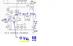
If you look into Papa’s Buffer to Blues, it has the input coupling cap (dc-blocking) and the resistor to the ground. These two are there because he wanted 10 Vdc to the gate of P-ch JFET and 13 Vdc to the source. He uses the feedback resistor forming dc-voltage divider with the R running to the ground to get the 10 Vdc. And, this is why the feedback line is inside the output coupling cap, referring to the 20 Vdc. The feedback resistor is working for two purposes: (1) negative feedback with Vac and (2) voltage divider with Vdc.
Meanwhile, in ZV8 or 9, Papa wants to have 0 Vdc at the gate of LU1040. Therefore, he does not need any DC voltage divider, and it explains why the beedback line is outside the output coupling cap. Instead, he is getting the necessary 0 Vdc from the ground via the resistors. In this case, too, the feedback resistor is working two purposes, but in a different way: (1) negative feedback with Vac and (2) a path referring to the ground voltage.
Maybe . . . I’m a babo as much as Papa . . .
No insisting, just an opinion . . . 🙂
I think that your current ZV7-T could be a complete amp only after being combined with the parts of the X-over circuit. Otherwise, it looks like an unfinished stand-alone amp.
If you look into Papa’s Buffer to Blues, it has the input coupling cap (dc-blocking) and the resistor to the ground. These two are there because he wanted 10 Vdc to the gate of P-ch JFET and 13 Vdc to the source. He uses the feedback resistor forming dc-voltage divider with the R running to the ground to get the 10 Vdc. And, this is why the feedback line is inside the output coupling cap, referring to the 20 Vdc. The feedback resistor is working for two purposes: (1) negative feedback with Vac and (2) voltage divider with Vdc.
Meanwhile, in ZV8 or 9, Papa wants to have 0 Vdc at the gate of LU1040. Therefore, he does not need any DC voltage divider, and it explains why the beedback line is outside the output coupling cap. Instead, he is getting the necessary 0 Vdc from the ground via the resistors. In this case, too, the feedback resistor is working two purposes, but in a different way: (1) negative feedback with Vac and (2) a path referring to the ground voltage.
Maybe . . . I’m a babo as much as Papa . . .
No insisting, just an opinion . . . 🙂
In post #206 of this thread I have a drawing of my buffer with some measured values. You'll notice that the buffer is delivering 8.7 volts to the IRF044 transistors. Mind you, I have two buffers, that's 8.7v x 2. I can play around with the source resistor and probably increase the voltage more, if need be.
This brings up an interesting thought: should the buffer be biased to operate at half the supply voltage? That would mean 14 volts out, not 8.7. Still, I notice that it only delivers 4 volts in the ZV4 project. Also, you'll notice that the Zen 4 amp has no input cap or grounding resistor.
Source followers are an interesting topic.
I'm interested in pursuing your ideas. I will report to the forum whatever data I may acquire.
Thanks again for all your help,
John🙂
It's almost three AM. I'm going to bed. Good-night.
carpenter said:Still, I notice that it only delivers 4 volts in the ZV4 project. Also, you'll notice that the Zen 4 amp has no input cap or grounding resistor.
No cap because the gate dc-voltage is 0
The feedback line is outside the output cap
R10 and R 20 look like the gnd resistors
I will no more intrupt your development
Enjoy 🙂
In post #183 you can see that the feedback resistor doesn't make it directly to ground, there's a cap in the way. Do you suppose this is why Nelson added the extra 221K ground resistor at the buffer's gate?
John🙂
Now I can go to bed.
John🙂
Now I can go to bed.
- Status
- Not open for further replies.
- Home
- Amplifiers
- Pass Labs
- ZV7-T (transformer)