
Just read through this thread and I have to say that I am intrigued. A ZOTL amplifier seems very appealing and I am surprised it hasn't found more traction, especially in the DIY space, but then again there are lots of people who think silicon and switching are the devil when it comes to audio.
Getting more or less the full power potential out of my tubes without needing big, heavy and expensive transformers seems absolutely excellent to me! Really opens up the possibility to make some wild stuff with esoteric tubes too if the design process isn't too bad. Maybe that's why it's not done much too?
Think I'll be giving this a try in spice come Monday at least!
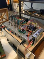
Started building yet another Zotl amp (dual mono) with some minor changes. Older version has a differential dc coupled driver stage.


It's been a few years, so I'm not sure if anyone is still following this. I've reproduced this model (from the image) and appear to get similar results at the nodes you've plotted, but I've noticed some odd behavior when I probe further. For example, it seems like the lower power source is suppling about double the current of the upper source and the switching waveforms are unusual. It could be an error on my schematic copying though. @savu is it possible that you could upload your LTSpice file and the libraries needed to go with it? I'd like to see why I can't seem to reproduce your results.Update:
Some corrections from the last simulation where I have completely forgot about tube bias.
I hope it sheds some light on how this topology works. I will need to consult with some smarter people and try to get back with a closer to reality simulation.
Silviu
Beware with simulations that models are in some cases somehow connected to a power source reference (ground).
Check all models for internal nodes.
Check all models for internal nodes.
So I am about to dip my toe in ZOTL. A question I have is how much primary induction do I need on the primary of the string of bridge rectifiers transformer? Berning in his patent gives an example of 3 turns on the primary and 5 turns on the secondary for a section. That seems to be very low. I will probably start with a carrier of 250khz.
On Rm12 core full bridge converter, a 3-turn winding is used for primary section and 8 sets of 12-turn winding are used for secondary section.
DCX used by Dave Berning is very special one. In 2006, there are just Doctoral thesis on this subject and some patents just awarded for this art.
"Electronic DC Transformer with High Power Density" by Dr. Martin Pavlovsky,is the thesis title. The new output-filter resonant converter

 (OFRC) is named and included as new kind of resonant converters. The load of this converter should have the current source characteristic and pentode just perfectly fit (in normal case, the additional filter inductor is inserted between filter resonant capacitor, C_r, and load resistance).
EPC-co had given the very good key waveform of the converter. This depicted that the diodes are operated in Zero-current-switching condition.
That why, only diodes with low junction capacitance work best with this type of DCX.
"Electronic DC Transformer with High Power Density" by Dr. Martin Pavlovsky,is the thesis title. The new output-filter resonant converter
EPC-co had given the very good key waveform of the converter. This depicted that the diodes are operated in Zero-current-switching condition.
That why, only diodes with low junction capacitance work best with this type of DCX.
A DC transformer model consisted of Epoly and Gpoly can be used to model Z converter of ZOTL. This is the circuit used in my LTspice simulation.

I understand the model of the amplifier thank you. What I have been trying to model is the impedance converter exactly as described in the patent. Using switches, coupled inductors for the transformers and ideal rectifiers. I would model the load on the rectifier with a modulated current source (pentode model). I will post my LTSpice model when I am at the point of giving up to simulate something that makes sense.
Got the LTspice ZOTL "Patent model" to work. This is mainly for me to understand DC-DC converter part of the ZOTL theory which I am new to.

Finally got a LTSpice model to run with decent times. I used idealized switches and diodes just to get the theory of operation confirmed. Got the single ended version running (below). Had issues getting a push-pull version working with real components. Next will try the idealized component version. Model below uses 4 rectifier stages and a current source to model the pentode load on the secondary. Switching frequency is 250 khz. Output is voltage on the 8ohm load resistor (10).

I think the switching voltage and current waveforms of DCX used in ZOTL never been reported to public (only on private social is shown)
Therefore, 3 cases are depicted in this post.
Test Condition: EL84pp (Pentode-mode), Low tension voltage was dual supply +/- 18 V and step-up ratio was 1:24.
1. No load condition when tube is off; only magnetizing current is observed in the primary winding current and EL 84's plate-cathode voltage shows some sign of self-capacitance in the tube.

2. Idle condition of EL84pp ZOTL amplifier:

3. Heavy load condition: Note that the current waveform has some similarity with Dr. Pavlovsky's Thesis (2006)

Therefore, 3 cases are depicted in this post.
Test Condition: EL84pp (Pentode-mode), Low tension voltage was dual supply +/- 18 V and step-up ratio was 1:24.
1. No load condition when tube is off; only magnetizing current is observed in the primary winding current and EL 84's plate-cathode voltage shows some sign of self-capacitance in the tube.
2. Idle condition of EL84pp ZOTL amplifier:
3. Heavy load condition: Note that the current waveform has some similarity with Dr. Pavlovsky's Thesis (2006)
What is the blue trace on the scope? And how did you generate the 250khz carrier square waves?
PS I started an LTSpice thread over here.
Right now I have since modeled a 6AV5 with screen drive in place of the idealized current source for the secondary load.
PS I started an LTSpice thread over here.
I am intrigued enough by the Berning ZOTL amp to actually try and build one. But before I do a working LTSpice model to understand the design was an necessity for me. So I created a model that matches his patent. I am sure there is many stuff left out of the patent that is important but discovering those in a simulation beats finding out on the bench. So this first attempt is an idealized model, switches instead of FETs, idealized transformers, but a real tube model (6NJ6 screen driven). So being totally new to ZOTL and screen drive this may be an interesting journey. The model does...
- jderimig
- Replies: 10
- Forum: Tubes / Valves
Right now I have since modeled a 6AV5 with screen drive in place of the idealized current source for the secondary load.
- Home
- Amplifiers
- Tubes / Valves
- ZOTL and ferrites