Biwiring won't change ( much at all ) how much current goes through the ( previously 7R ) now, 12R resistor.
- Use a 10 watt ( or greater ) resistor.
The 1.25uF cap is wired over top of ( bypassing ) a "T" pad formed by 3 resisitors ( look at my last posted drawing ).
- The T-Pad is indeed there to reduce the level of the horn ( the 1.25uF cap allows a bit of UHF content to bleed past the resistors ).
The 1.65uF cap sets a 6db per octave roll-off point ( + it's actually very high in frequency where it kicks in rolling off the lower frequencies ).
- The caps initial roll-off point is different from the crossover point ( btw ).
That 1.65uF cap rolls off the horn at 6 db per octave ( but because it starts high, at say 10K ) it merely flattens out the natural 6db downward ( forward ) slope of your "raw" horn driver response before the builtin LF rolloff of the horn/driver combo kicks in, adding another 6 db per octave ( acoustic ) rolloff on top of the 6 db electrical rolloff .
- The individual acoustic + electrical rolloffs combine to give a final rolloff of 12db or more .
🙂
Hello EarK. This is fascinating, thanks a lot.
I read possibly different crossover system, that a 2 way with caps and resistors combo work together to create a resistance value at a certain frequency.
The Crossover - Brain of your Loudspeaker System | Audioholics
So if I understand my circuit, I have 3 resistors on the negative leg after the 1.25uF cap, and 2 resistors on the positive leg, which work with the cap to set the FR and crossover point?
I was wanting to avoid shifting the 1000hz cross over point, as that may send some upper bass data to the horn.
Anyone still around to help?
I am super happy with my upgrade / rebuilt crossover.
But i am confused about the resistors as R1 and R2, which I reduced from 20R to 10R, these are in parallel to a drop overall from 10R to 5R either side of the smallest cap which is 2.22uF.
Does R1 and R2 increase the current to the highs, and does it also move the crossover point up or leave it as is?
I have about 3-4dB gain increase on the HF circuit which seems perfect for my room. I also increased R3 from 7R to 12R as was advised this should 'suck' more current to the highs circuit.
My crossover point is stated at 1000hz by Zingali. I have played a full FR sweep, and a more restricted 2K-800hz sweep, and it seems very smooth, no peaks or dips.
I am also wondering if there is a reason to update / upgrade the aircore inductors. There is only one per speaker. It is about 60mm wide x 50mm high and is copper wire about 1mm. And has a plastic core. It is not potted or varnished.

I am super happy with my upgrade / rebuilt crossover.
- I thought your smallest cap had a value of 1.25uF ( did that change ) ?But i am confused about the resistors as R1 and R2, which I reduced from 20R to 10R, these are in parallel to a drop overall from 10R to 5R either side of the smallest cap which is 2.22uF.
Does R1 and R2 increase the current to the highs, and does it also move the crossover point up or leave it as is?
- Reducing the value of R1 +/or R2 allows more signal to reach the compression driver > therefore the HF ( proportionally more hi-mids than UHF ) gets louder.
- Increasing R3 just stops voltage from draining to ground ( which deprives the horn driver of signal ).I have about 3-4dB gain increase on the HF circuit which seems perfect for my room. I also increased R3 from 7R to 12R as was advised this should 'suck' more current to the highs circuit.
- Increasing R3 has the same effect ( to a point ) as decreasing the values as R1 or R2 .
- I figured you would get about 4db more horn output.
My crossover point is stated at 1000hz by Zingali. I have played a full FR sweep, and a more restricted 2K-800hz sweep, and it seems very smooth, no peaks or dips.
Think about it; as the horn level goes up ( in relation to the woofer ) it's going to intersect the woofers output at a lower & lower frequency ( acoustically ).
- You don't need to worry about this because the electrical rolloff is set so high ( > 10K ) that ( electrically ) the signal is already @ 28db down ( at 1K ) and about 40db down at 250hz ( with the recent changes to resistor values ) .
I am also wondering if there is a reason to update / upgrade the aircore inductors. There is only one per speaker. It is about 60mm wide x 50mm high and is copper wire about 1mm. And has a plastic core. It is not potted or varnished.
I would only change out that inductor if it has loose windings and is noticably starting to "sing-along" ( resonate/ buzz ) along with the music.
- One can mitigate that by dipping the inductor in wax.
🙂
Last edited:
Hey that is great information there. Many thanks. I think I am good with this mod now then. I don't think I need to do anything more on it. I don't hear any vibration or distortion in the bass speaker. I have tested it quite loud as well.
Yes I ended up with 1.22uf on the last cap, as I couldn't find a decent 1.25uf. I guessed it was close enough to tolerance.
I did think about potting the inductor. Might be a cheap way to update that. But may change the electrical field of it?
I figured the sound quality to gain from an inductor swop out may be less than gains I have heard from the mids and highs out of the horn.
The crossover work has transformed my speakers, which were retail 17K euros back in 2009. The caps were very basic, holding it back I think.
Thanks again Earl you have been great!
Julian
Last edited:
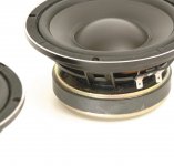
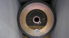
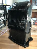
I am the happy owner of the Zingali Overture 2s that Astrostar59 owned before his present ones. He has sent me the link to this thread, and I am bitten with the bug to upgrade my crossovers. My Overtures are of a similar age, and have a quite large ferrite magnet compression driver and an 8" woofer. Does any one have any idea about the manufacturer of these drive units please? I'll try uploading a picture of the insides.
Today I downloaded the Xsim software and it's really fun. Earl can I prevail upon your kindness to point me to suitable models for these to go into the Xsim?
Today I downloaded the Xsim software and it's really fun. Earl can I prevail upon your kindness to point me to suitable models for these to go into the Xsim?
<<<<SNIP>>>>
Today I downloaded the Xsim software and it's really fun. Earl can I prevail upon your kindness to point me to suitable models for these to go into the Xsim?
I used ( as standins for XSim ) frd + zma files created by Zilch ( RIP ) and sourced from HERE!
I figure the horn driver is likely a B&C de10 crossed to some 8" woofer that's made by an italian pro driver manufacturer ( such as RCF, B&C, 18Sound, etc. etc. ).
Try the ( frd's + zma's ) from Zilch's S8 mini project ( though I think what's really needed here is a de10 driver on some 8-10" wide axi-symmetrical > round horn ).
Yes, you should post some pics.
🙂
Attachments
Last edited:
Thank you Earl, that is really useful. Today for a change I have been making a small brick wall in the garden. This evening I have opened up the Overture 2 and have put the values into Xsim. The actual resistance of my bass and horn units is 5ohm, so I’ll have to hunt for something more realistic. I made up the 1mH inductor value.
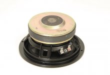
The drive units are about 15 yrs old. Last year the bass unit foams disintegrated and I got them re-foamed. Bass magnet is 130mm dia, horn 90mm.
I would post some more pics but my files are too large. Try again tomorrow.
The drive units are about 15 yrs old. Last year the bass unit foams disintegrated and I got them re-foamed. Bass magnet is 130mm dia, horn 90mm.
I would post some more pics but my files are too large. Try again tomorrow.
Attachments

Last edited:
Thanks for the pics.
FYI, the dcr value of the B+C de10 is just over 5 ohms ( and has a 90mm diameter magnet ).
I suspect that your woofer was custom built for Zingali.
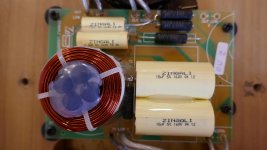
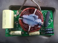
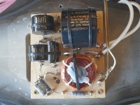
I'm confident that the pictured inductor has a value quite a bit more than 1mH.
- It appears that Zingali wound their own air-cores and then added ferrite rods ( inside the air-core ) to raise the value of inductance.
- The 4 ferrite cores that I see ( under the silicon goop ) should more than double the value of the original air-core coil.

What exactly are you wanting to accomplish with your proposed crossover modifications?
🙂
FYI, the dcr value of the B+C de10 is just over 5 ohms ( and has a 90mm diameter magnet ).
I suspect that your woofer was custom built for Zingali.
I'm confident that the pictured inductor has a value quite a bit more than 1mH.
- It appears that Zingali wound their own air-cores and then added ferrite rods ( inside the air-core ) to raise the value of inductance.
- The 4 ferrite cores that I see ( under the silicon goop ) should more than double the value of the original air-core coil.
What exactly are you wanting to accomplish with your proposed crossover modifications?
🙂
Thank you Earl. I agree with what you say about the inductor. I only put in a low value to make it look good on the FR. The other thing is that I had to do is reverse the phase of the horn. But on the real XO it does not appear to be reversed. This simulation does not bear a real correlation to the Zingali bass unit.
No doubt there is not a set of .frd and .zma data for the Zingali bass unit available. I suppose if I wanted to model this accurately I would have to measure the FR and Z curves myself. So quickly getting in deeper!
I love this loudspeaker so would be interested in extracting the maximum from it.
Objectives would be;
1. to substitute better components in XO.
2. Modelling accurately enough to suggest slight component tweaks. (and for technical interest/understanding)
As I have not tried this modelling before, I am open to any suggestions for software/techniques.
Result of my activity on these speakers over recent days;
1. I have changed the HF pass components to better ones of same or closest value. Namely ClarityCap CMR and Mills non-inductive, non-magnetic resistors. The result is notably changed HF energy, speed of attack, more noticeable small details, room acoustic. Piano sounds the best I’ve heard for example. There is so much increased HF energy coming through that I am thinking I might need to reduce the level by a fraction. I have not changed the bass components at all although there is a perception that the bass is a bit faster and better defined. Possibly faster rise times are causing this. Objective is already well on the way to being satisfied. PS I have removed the original components from the pcb and added the new ones. I was keen to hear the results so they were put straight back in the enclosure. When the results of the tweaking are final I will rebuild the XO, and post some views then.
2. I would need to get measurement kit and do a lot of investigation to satisfy this objective and as the speaker is already very satisfying I shall not attempt this at the moment.
Last edited:
It sounds as though your main change may have been the treble level.
It also seems as though your blend is close but not spot on. This can result in small changes in level making some parts sound better and some parts becoming too loud.
It also seems as though your blend is close but not spot on. This can result in small changes in level making some parts sound better and some parts becoming too loud.
It sounds as though your main change may have been the treble level.
It also seems as though your blend is close but not spot on. This can result in small changes in level making some parts sound better and some parts becoming too loud.
Yes definitely. Most well recorded music sounded very clean and revealing but a couple of older or poorer recordings were a bit fierce showing recorded distortion. I like the increase in energy which seems to go into the mid band though.
Using Xsim (although I do not have a true driver model) to see what I could mod to tame the high end a tiny bit. C2 being the likely candidate first.
( Looking at your posted XSim schematic ), simply make R3 smaller in value > to bring down the horn level to a more desirable balance ( resistors being much less expensive than audiophile caps ).
In fact, one could wire a 30 ohm variable resistor in parallel to the existing 4.3R wirewound ( and then adjust to taste ).
From looking at the overall response of the Overture 4 ( within the pdf I posted earlier ) , I suspect your Contour 2 also has a bit of a jacked up driver level ( due to sharing the same family name + most likely using the same compression driver ).
🙂
Attachments

Last edited:
me said:From looking at the overall response of the Overture 4 ( within the pdf I posted earlier ) , I suspect your Contour 2 also has a bit of a jacked up driver level ( due to sharing the same family name + most likely using the same compression driver ).
Oops Sorry, meant to say "Overture 4" there within that last post.
If you want to proceed further down the proverbial "rabbit hole", you can do that pretty simply by loading an audio testing app on your smart-phone && then start looking at the overall response of your speaker ( to decide if there are any areas that you might like to improve upon ).
I have on my Android powered phone an app called Audio Tool.

To "believe" any response obtained above ( say ) 3K and below 200hz, one should use an external test mic ( + one that provides a calibration/correction file for the mic ).
The Dayton iMM-6 is a decent choice.
Say you were to test a single speaker ( done on the listening axis, at around 1 meter away ) and you found a similar large "suckout" between 1K and 2K as seen in the Overture4 ( > present, no matter if you test above or below the listening axis ) > then you could always disconnect ( one end ) of 1 of those twin 15uF caps ( in the bass section ) to see if some of the mid area gets restored ( it should ).
- Additionally, shorting R4 ( the 5R resistor ) will bring back even more midrange ).
I wouldn't recommend trying these tweaks until you have some ( at least basic ) test gear in place ( since testing will confirm what FR changes were made ) .
🙂
Yes I’m entirely with you on adjusting the 4.3ohm and I have been digging out some old variable resistors to do it. I am thinking that I want to maintain the mid /lower HF but roll down the higher frequencies a bit so might have to change the C but will adjust the R first.
Thank you, Earl that is what I hoped to know for starters. I am out of touch with what is available –so many useful tools now exist.
Your suggestions and info are very helpful – if I do fall down the rabbit hole I’ll post here.
Thank you, Earl that is what I hoped to know for starters. I am out of touch with what is available –so many useful tools now exist.
Your suggestions and info are very helpful – if I do fall down the rabbit hole I’ll post here.
Last edited by a moderator:
Hi Guys, and Geoff! You were modding my previous Zingalis here.
I also modded my Client Name Evo 1.2s with Mundorf Silver/Gold Supreme caps, silver hard wired on wood board, and tweaked the resistor values a bit. I originally wanted more transparency and attack. After the caps burnt in, I did indeed get that. And it was bang on.
However, I have changed my power amps and they are now a bit too hot in the treble. I probably need to:
1. Back off the level of the horn a bit
2. Possibly ease back the upper treble a bit, maybe by 2dB range.
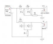
Here is the circuit, sorry for my basic stick drawing. Hopefully you get the signal paths.
I have marked the original Zingali values, then my values. I got some help on here on how to increase the horn level by changing the
I also modded my Client Name Evo 1.2s with Mundorf Silver/Gold Supreme caps, silver hard wired on wood board, and tweaked the resistor values a bit. I originally wanted more transparency and attack. After the caps burnt in, I did indeed get that. And it was bang on.
However, I have changed my power amps and they are now a bit too hot in the treble. I probably need to:
1. Back off the level of the horn a bit
2. Possibly ease back the upper treble a bit, maybe by 2dB range.
Here is the circuit, sorry for my basic stick drawing. Hopefully you get the signal paths.
I have marked the original Zingali values, then my values. I got some help on here on how to increase the horn level by changing the
Attachments
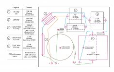
So I need some advice on what I need to alter on the resistors, to reduce the horn gain a bit. Is it resistor location 1, or the pair at location 2?
Once I can get the horn gain down a bit, then I can see if I need to tame the upper treble a bit. I also thought about trying a pot on the R1, if that is the location, to tune it live, them add a fixed R after I know the value.
Thanks so much for your help guys!!
Once I can get the horn gain down a bit, then I can see if I need to tame the upper treble a bit. I also thought about trying a pot on the R1, if that is the location, to tune it live, them add a fixed R after I know the value.
Thanks so much for your help guys!!
More advice needed please, to get even more...
On my Zingali Client Name Evo 1.2s, they use a DE400TN 16 ohm 44mm 1 inch throat (mounted) compression driver by B&C Italy. 107dB efficiency. It comes in at 1200hz right up to 20K! It actually starts to tail off after 10k, indeed loosing output from 5-6k.
SO.... I am thinking I can extract even more performance out of these speakers. As luck would have it, B&C make a DE550TN 16 ohm 51mm 1 inch throat compression driver which has more power handling, up from 100W to 140W. And the FR is slightly better in the crucial 5-12K region. Rest is the same, very close to the DE400TN model. So should work ok with the existing crossover, and will fit the mounting as well.
Imagine I will need to adjust the T pad values a bit, as the 550 has 108dB. And being new may have bit more output?
The bigger driver will possibly be less stressed and more dynamic, a step up from the DE400 I am thinking. Zingali never used this driver, but it is new, so probably why.
The existing Zingalis are really good, great sound. If I can get even more out of them, maybe bit more midrange details, and smoother treble roll off, I can then reduce the T Pad down a bit, and bring up the mids a bit. That is my idea.
Thoughts?
Attachments
- Home
- Loudspeakers
- Multi-Way
- Zingali 2 way crossover help needed!!!!!