i have just known about Zhaolu D/A converter.
Sometime i will try to go to the store in bangkok and listen it recently. if it's good. i will buy and play with my DVD.
😉
Sometime i will try to go to the store in bangkok and listen it recently. if it's good. i will buy and play with my DVD.
😉
I've been investigating some sound quality issues that have surfaced lately with my Zhaolu 2.5A Dac, well the problem is that my modified Sony SCD-777ES SACD player is absolutely creaming it on red book cds sonically speaking, to the point that the Zhaolu sounded broken. Now the Sony is more than slightly modified, but the differences are so profound on a/b via spdif coax to the dac and the analog outputs of the Sony - and the results are virtually identical playing the same material via the media server until I upsample to 24bit 96K where the audible differences are less but not gone - the Sony still wins by some margin. Incidentally the Sony's are regarded as quite good transports in their own right, unfortunately I do not have another dac to compare with. The Zhaolu sounded far better at the time than the PS Audio Ultralink II which I subsequently sold.. The Sony is far quieter, shockingly so, and you may not even understand what I mean - the background is black, there is a lot more micro-detail, and it just sounds much better..
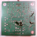
I took the dac apart tonight and discovered that the power supply board is full of pcb layout errors. The grounding scheme is somewhat messed up. I discovered that the transformer center tap is grounded to multiple points on the board, and that the only way to fix it is to remove con1 on the board and looking from left to right cut the 3 tiny etches that go from pin 4 to the board ground plane on both the top and bottom - this at least removes one error in the board grounds. More work is needed and I will add detail as I figure out how to fix some of these mistakes.
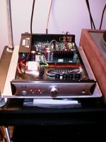
The chassis is also part of the grounding system for the digital portions of the dac, and I found adding a copper foil plane in the chassis improved things audibly. I had to remove all of the stand-offs to do this, and there are a lot.. 😀
I also added the missing safety ground that others mentioned and checked the AC leakage for both normal and inverted ac polarities and could measure no difference in leakage current with the Keithley 2002.. (ground not connected obviously) So I left it as it was.
Still doesn't sound good next to the Sony, but it is definitely a little closer.
I took the dac apart tonight and discovered that the power supply board is full of pcb layout errors. The grounding scheme is somewhat messed up. I discovered that the transformer center tap is grounded to multiple points on the board, and that the only way to fix it is to remove con1 on the board and looking from left to right cut the 3 tiny etches that go from pin 4 to the board ground plane on both the top and bottom - this at least removes one error in the board grounds. More work is needed and I will add detail as I figure out how to fix some of these mistakes.
The chassis is also part of the grounding system for the digital portions of the dac, and I found adding a copper foil plane in the chassis improved things audibly. I had to remove all of the stand-offs to do this, and there are a lot.. 😀
I also added the missing safety ground that others mentioned and checked the AC leakage for both normal and inverted ac polarities and could measure no difference in leakage current with the Keithley 2002.. (ground not connected obviously) So I left it as it was.
Still doesn't sound good next to the Sony, but it is definitely a little closer.
Update...
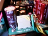
There is a 2200uF/25V G-Luxon cap on the left hand side of the power supply board with a direct connection back to the transformer center tap that I did not cut the last time around. This time I cut the etch on the top of the board to this cap ground and ran a wire directly from the negative side of this cap to the mecca ground between the two analog supply 3300uF caps - this plus replacement with a generic rubicon made a big difference. (This change makes the transformer center tap go directly to a point common the grounds of all three filter caps powered by this winding and from there to the board ground - it keeps all of the charging currents confined to well defined paths.)
I also shorted various of those "ground traces" to the ground plane with wire and solder as opposed to the thermal decoupled through holes that exist. I just did the ones by the all of the regulator output caps.
Much cleaner, and now sounds a bit closer to the Sony analog outputs. The Sony still wins hands down, but it is not embarrassing as it was before. (This was a substantial improvement and should be audible on any 2.5A or 2.5C I suspect.)
Kevin
What output buffer are you using with the 2.5AD?
Is it the standard one?
I also gather your driving the 2.5 via spdif from the sony.?
What is the spdif coupling like, some of the standard manufacturers implementations leave a lot to be desired.
allan
ps All ears on the ground mods, i was thinking about a piece of copper/brass bar to run as a star ground.
Hi Alan,
I am using LM4562 op-amps which made a huge improvement over the stock op-amps, and the ones diykits fitted upon shipping.
The Sony has a transformer and a very good spdif driver circuit.
The dac sounds exactly the same with the media server as a source..
Finally making the changes I listed in the previous post to the power supply and chassis made a huge difference. The Sony is killer, and I have far more money into it than the Zhaolu (both acquisition and mods) but the Zhaolu sounded just terrible by comparison - now it actually doesn't - clearly not quite as good, but much closer. (It's less precise, has more diffuse imaging, sloppier bass and a bit fuzzier, grungier presentation overall - but it is massively better than before.)
The 2.5A which was a major improvement over both the PS Audio Ultralink II and the Assemblage DAC 1 I had. (Plus several other not so cheap recent competitors.)
More rework detail:
I have a very poor digital camera that will not provide detailed pictures for this mod. The mod consists mainly of removing the transformer secondary connector on the pcb, cutting six little whisker sized etches around con1- pin4 (transformer center tap), reinstalling the connector, replacing the 2200uF cap with something decent and cutting an etch to its negative terminal on the top side of the board and jumpering it directly to the ground "mecca" on the bottom side of the board between the two large 3300uF supply caps to the analog supply.
Finally if you look very closely you will notice the ground side of all of the components in the analog supply and some of the clean analog supplies to the digital board have tiny little whiskers to the ground plane, and odd traces that run all over the board and are grounded at multiple points on the pcb - these shouldn't exist at all. (These are thermal through hole pads incorrectly implemented.) Just scrap some of the mask away around the adjoining ground plane and solder some wire across this point. I did it near to the output caps of the +15/-15V and the dac's analog supply as well.
Get some thin copper foil or sheathing (home depot, etc) and remove all the stand-offs, fit to chassis and drill holes where the screws need to pass through, reinstall the stand-offs loosely and then install the boards - once everything is aligned properly tighten everything snuggly.
I am going to figure out how to reconfigure the muting relay to shunt the output, currently it is in series with the output signal, not the best thing for clean sound.
Also I have not replaced the POS output jacks, and this is needed desperately.
Hope this detail helps..
Kevin
I just had a look at the 2.5AD again(it's been sitting unused for a while).
trying to trace tracks at present, first thing i noticed, the coax and optical input, no transformer coupling, input from rca goes into a 10uF sm cap, bypassed with a 0.1uF sm cap then into a 74hcU 04d.
the 74**** is ok but the coupling caps🙄
Will look further to try to trace grounds.
I prefer to separate analogue and digital power and grounds as much as possible until a star earth
allan
Hi Alan,
Take a very careful look at the power supply board as there seem to multiple problems with the grounding arrangements. I found 3 separate places where the transformer center tap was grounded to the board, and all those etch cuts I described were just to address that one issue. (It really does help.)
The other thing is the way that thermal vias are used to make connections to the ground plane, and that there are often traces between each of the components connected to the plane on the ground side - each trace being connected to the plane at the thermal via. These particular thermal vias have relatively high resistance connections to the plane, and I think it is worthwhile to fix this by at least shorting across the trace to the plane in one place - I choose the output caps - I didn't try to cut all of those whisker thin etches though because there are a lot of them..
It's a cheap dac, so I am not surprised that there is no input transformer, since there is no clear convention about where transformers are used and I think several of them in the spdif signal path is probably not a good thing I am not too disturbed by this.
Both the Sony and my media server have transformer coupled spdif outputs.
The toslink input sounds far worse incidentally than the spdif input, but I find it useful to have, but this probably does point to a less than optimum input receiver configuration.
I replaced that G-Lukon 2200uF cap with a much lower esr/esl rubycon and I think this helped as well.
The copper foil also seems worthwhile because this is a steel chassis and many of the standoffs go to ground points on the digital board as well as the power supply board, over time I suspect corrosion would compromise these grounds, not to mention the powder coat overspray all over the inside of the chassis. Steel isn't a particularly good conductor particularly at high frequencies so I think the copper foil is a good idea. You can use copper sheathing from a local home center, and that might be even better. (Probably brush some clear varnish on the foil/sheathing after installation to keep it from corroding?)
If anyone has the schematic for this dac it would be most useful, just email it to me.. 😉
I think I am going to upgrade some of the electrolytics in the power supplies, output decoupling in particular, and take a look at the ones on the audio board as well.
I am going to replace all of the rca's in this thing with vampire jacks shortly, and further mods to the audio path are in the offing.
I was pretty thrilled with this dac when I got it (for reasons I've previously mentioned) but I have to admit I am more than a little disappointed upon delving in further to discover that a lot of the potential is lost due to errors in the board design that could have been easily avoided and at 0 cost. It looks to me like several people worked on the layout and the power board appears to be the worst - however I have not really looked at the digital board and have spent very little time on the audio board as of yet.
Now that it is not my primary music source I have the luxury of modifying it for improved performance, and importantly something to compare it to.
Thank's Kevin
I did notice the multiple earths on the psu.
I'll remove some parts on the psu and try to follow the tracks.
the copper might be the easier way to do it, just earthed at certain points.
The spdif transformer coupling, or other was based on Jocko's ideas spread around various post's in this forum.
I'll see what i can find and link them.
The CS8416 is not that special on jitter, just need to find the best way of limiting the damage.
This Dac is better than the average cdplayer outputs but when some players are modded well, you start noticing this dac's limits.
allan
awpagan said:Thank's Kevin
<snip>
This Dac is better than the average cdplayer outputs but when some players are modded well, you start noticing this dac's limits.
allan
Hi Allan,
I'd definitely have to agree with that last comment... 😉 The changes I've made as outlined in my previous posts do make a very audible improvement, and it no longer sounds broken, but it doesn't sound very good compared to my modified scd-777es either. It's a bit strange because when I first got it I was very impressed over the improvement compared to two other dacs that I still owned at the time, and a dac I had in for a possible review that cost about 7x what the Zhaolu did.
All I can say is I guess I don't know (or didn't know) what relatively good digital could sound like - or it's possible that the dac's performance has deteriorated significantly in the 14 months I've owned it.
I think if you look at the power supply design and follow the notes I posted here you will be able to fix the ground loop that the transformer center tap connection creates.
I have also determined that all of those little Elna red 47uF caps are 16V parts and are operating with 15V on them - not too good for long term reliability. I am going to replace these with one of the intermediate grade Black Gate in the same values, but with 25V ratings.
I also noted that there are two large ferrite beads on the analog supplies to the op-amps on the audio board. I am going to physically remove and jumper those. What is the point of having a low impedance supply if you have those in series with it? I will probably omit one pair of the electrolytics as well.
Analog_SA made some comments about the design of the digital board which I totally agree with, but I'm afraid that the digital board is probably the high point in this dac's design, and everything else is relatively poorly executed when you look closely enough.
Incidentally on the digital board there are two large smd electrolytics right near the audio output, these are actually filters for the reference and other internal analog nodes and I am planning to change these to Black Gates as well. (The pads are big enough.)
The audio board needs lots of work, and I am thinking of replacing all the resistors in the diff amps because of the poor matching - there are gains to be made in cmrr which will reduce distortion at the outputs, and feed through of common mode quantization noise.
I know in recent months I have been listening to analog almost exclusively - I was just tired of the digital side of the system. Getting the scd-777es and doing some mods has been a real eye opener. Good sacd recordings sound better than any cd I have ever heard, and cds sound better on this player than anything on the server through that dac.
I have a 2.5C that I have recently modded. I'm most interested in your changes to the grounding scheme - but a picture would say a whole lot about the changes you made.
On the output board, I have also found that the LM4562 op amps are very transparent - perhaps overly so. They sound best when the coupling caps are left in the circuit, and too bright when the coupling caps are removed or jumpered.
I found a nice balance using OPA2107 op amps when the coupling caps are jumpered. Thanks to Paul Kap for this suggestion.
I also found far better sound using the TOSLINK input over the RCA digital in. One modder is selling his mods to the general Zhaolu marketplace (Oritek). He uses a torroidal transformer on the RCA digital input. Any ideas to the value of this and where to pick one up? It looks fairly straightforward to implement, based ont he picture on Oritek's website:
Enjoy,
Bob
On the output board, I have also found that the LM4562 op amps are very transparent - perhaps overly so. They sound best when the coupling caps are left in the circuit, and too bright when the coupling caps are removed or jumpered.
I found a nice balance using OPA2107 op amps when the coupling caps are jumpered. Thanks to Paul Kap for this suggestion.
I also found far better sound using the TOSLINK input over the RCA digital in. One modder is selling his mods to the general Zhaolu marketplace (Oritek). He uses a torroidal transformer on the RCA digital input. Any ideas to the value of this and where to pick one up? It looks fairly straightforward to implement, based ont he picture on Oritek's website:
An externally hosted image should be here but it was not working when we last tested it.
Enjoy,
Bob
BobM said:<snip>
I also found far better sound using the TOSLINK input over the RCA digital in. One modder is selling his mods to the general Zhaolu marketplace (Oritek). He uses a torroidal transformer on the RCA digital input. Any ideas to the value of this and where to pick one up? It looks fairly straightforward to implement, based ont he picture on Oritek's website:
An externally hosted image should be here but it was not working when we last tested it.
Enjoy,
Bob
Hi Bob,
That's an interesting comment, my experience has been quite the reverse, and I never use the toslink for critical listening as for any source I have tried that had both was clearly better sounding on the coaxial input. (These days that is the Sony player mentioned) Incidentally both of the sources I use the Zhaolu with have transformers in their output circuits.
The spdif input circuit is a bit different than I usually encounter in that it is buffered by that 04 chip which is connected as an analog inverting amplifier. Why they didn't go directly into the input receiver of the 8416 I don't know - it's a good one and I doubt the buffer is an improvement, but I could be wrong.
Unfortunately I don't have a digital camera that is able to photograph traces of 0.025" width and won't have one soon. What I can tell you is to take out con1 and count four pins to the right and with a loop look at the pad - you will see 3 tiny little etches between the pad and the ground plane - cut these. Next turn it over and cut the 3 on the bottom side. This is the center tap of the only winding on the transformer that has one.
Next from the top side remove the 2200uF G-Lukon electrolytic cap and discard it. Cut the etch topside (anywhere) from Con 1 pin 4 to the negative side of this capacitor. Next install a better 2200uF (Elna/BG whatever) here and solder a wire from the negative terminal on the back side of the board to the middle of the mecca point where the two 3300uF Elna caps feeding the analog supplies are located. This looks like a big T that goes directly to the middle mounting standoff pad.. Solder a piece of braid from the pad to the adjoining ground plane. (Make sure it does not interfere with the standoff causing the board to bend.) Reinstall Con1.
There won't be any pictures of this mod, because my camera does not have sufficient resolution to show it clearly. Anyone else who does this mod please feel free to post it here.
If you remove the power supply board the issues I mentioned should be very obvious.
You can purchase good spdif transformers made by Newava from digikey. You want the S22160 which has around 15pF of interwinding capacitance and relatively low leakage inductance. Don't make the mistake of going for a low capacitance version as they usually have higher leakage inductance and poor high frequency response.
Contact Oritek for information on where to buy their products.
I installed N type blackgates to replace the stock Nichicon Muse, and found them not to be a particular improvement over the ones that were there. Like you I did not like the result when jumpered with the 4562 or even with any other op-amp I tried. The AD1852 based 2.5A sounds different than the 2.5C version so my comments should be construed as applying to the AD1852 version only.
The direct dc connection to the input of the diff amp forces the dac to source over 1.2mA dc to each of the inputs, which may or may not help the linearity of the dac op-amp, and also puts 2.5V of common mode dc on the input of the diff amp which shifts the operating conditions of the input stage significantly - it may or may not be an issue, but some input parameters may degrade when used this way. Were I to do this I would change all of those 1K resistors in the diff amp to 10K, and the scale the input filter caps appropriately. I might try it at some point as I am not too impressed with those cheap metal film CN55 resistors in the analog board.
Well I did some more work on the dac only for it to get clobbered by the Sony again. (Consensus of my friend Nick and I) Still it has improved and here are the latest mods.
I removed the two ferrite beads, and reconfigured the muting relay to shunt the outputs.
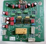
Just cut out the two 10 ohm resistors on the top near the op-amps, hard to miss as they are the only 10 ohm resistors on the board. Solder 100 ohm resistor from pin 7 of each op-amp to the appropriate pin on the relay as shown below.
I removed the relay on the outside edge of the board, this one feeds the headphone amplifier which I will not be using in the future.
I also ripped out the crummy rca jacks and replaced them with a single pair of tiffanys I had on hand.
The traces on this board lift very easily compared to the power board and the copper seems very thin.
This modification did help significantly, slightly narrowing the gap. Nick thought the dac sounded a bit brighter overall than the Sony, but that unfortunately it lacked the clarity and detail of the Sony. I agree.. Most of the odd colorations and grittiness previously audible are gone, the highs are a little cleaner, but the ultimate level of resolution is audibly (and vastly) inferior to the Sony scd-777es analog output. Connected to the server and playing the same music ripped from the same disk the result sounds identical as best we could determine and does not get any closer to the level of performance we heard from the Sony analog outs.
I would say this is a good dac, not a great dac, but the others I had previously must have been worse I guess.
I removed the two ferrite beads, and reconfigured the muting relay to shunt the outputs.
Just cut out the two 10 ohm resistors on the top near the op-amps, hard to miss as they are the only 10 ohm resistors on the board. Solder 100 ohm resistor from pin 7 of each op-amp to the appropriate pin on the relay as shown below.
I removed the relay on the outside edge of the board, this one feeds the headphone amplifier which I will not be using in the future.
I also ripped out the crummy rca jacks and replaced them with a single pair of tiffanys I had on hand.
The traces on this board lift very easily compared to the power board and the copper seems very thin.
This modification did help significantly, slightly narrowing the gap. Nick thought the dac sounded a bit brighter overall than the Sony, but that unfortunately it lacked the clarity and detail of the Sony. I agree.. Most of the odd colorations and grittiness previously audible are gone, the highs are a little cleaner, but the ultimate level of resolution is audibly (and vastly) inferior to the Sony scd-777es analog output. Connected to the server and playing the same music ripped from the same disk the result sounds identical as best we could determine and does not get any closer to the level of performance we heard from the Sony analog outs.
I would say this is a good dac, not a great dac, but the others I had previously must have been worse I guess.
Attachments
Kevin
What dac is in the sony?
Is it discrete output?
On the analoge pcb, it still uses multiple earths.
Also try to separated the digital and analogue earth.
on the analogue pcb, the dac input is +, -, gnd on both channels.
star earth the input gnd, so any digital noise is not contaminating the analogue circuit.
I havn't tried it myself on the Zhaolu, but on my optus with discrete it worked wonders..........
allan
The Sony is fully DSD, and up converts CDs to DSD. Has no industry standard parts you'd recognize. The analog stage is mostly op-amps with a hybrid (op-amp and transistor) output stage. This unit was one of their two flagship players when they first introduced the SACD.
Apparently little expense was spared on the design(s) and they got it mostly right, quite an industry has sprung up around modifying these players. I've done a fair amount of modding on it, but have basically stayed with the Sony design. I have a thread about this player here:
http://www.diyaudio.com/forums/showthread.php?s=&threadid=113142&perpage=25&pagenumber=1
I'm going to take a look at the grounding arrangement on the digital board. Best practice these days is considered to generally be a single plane with a local analog ground at the dac which connects at one common point very close the device, and based on noise measurements I've done at work on several data acquisition systems I've designed (ate) this seems to be true.
I've ordered parts for some cap upgrades in the audio and power supply boards. (Mostly 47uF BG) I have also ordered a bunch of the original Holco H4 1.02K (1K no more stock) to replace the originals in the diff amps with - it will be a tight fit. I also plan to make some changes to improve cmrr in the diff amp stage.
I'm going to move the ground on the analog inputs on the audio board and take a closer look at the digital board.
Will update once the parts get here.
Kevin
I'm going to move the ground on the analog inputs on the audio board and take a closer look at the digital board.
Will update once the parts get here.
Kevin
Member
Joined 2003
Wow, you're right Kevin, I opened up my Zhaolu 2.5A yesterday and the PCB layout of this DAC is atrocious. Looks like I have a lot of work ahead of me with a soldering iron and an exacto knife.
I notice in many places I see parts which are grounded to the ground plane on both the top and bottom of the board. That is, the part connects to a via which connects to ground on the top and bottom. What are your thoughts on this? Is there any gain to be had from removing one of these ground connections? I see many instances of this on all three boards (DAC, PSU, and analog).
I notice in many places I see parts which are grounded to the ground plane on both the top and bottom of the board. That is, the part connects to a via which connects to ground on the top and bottom. What are your thoughts on this? Is there any gain to be had from removing one of these ground connections? I see many instances of this on all three boards (DAC, PSU, and analog).
- Status
- Not open for further replies.
- Home
- Source & Line
- Digital Line Level
- Zhaolu DAC - a good value DAC?