Yes, the problem here is that it is made for a 60mm fan, so that will drop straight in, so I think I will start with that.
I replaced the fan, and reduced speed and noise with a series resistor, so now I can't hear the fan from the listening position. Temps are slightly higher, but hopefully still safe..
I have also dared to connect them to my main speakers using passive xovers (4ohm load) and listened to them for a while. They do have a different character compared to the others I've been testing.
Bass is 'fuller' but not as controlled as with many other amps. I guess that could have something to do with a higher output impedance raising the Q on the bass alignment. Sounds nice, but not as precise as I like it.
Mids and highs are all nice and a bit 'mellow/laid back'. Almost like lacking treble, but it's still all there, and in complex music (progressive metal, yes there are some decent quality recordings of that too) all the instruments are there, so it's not all a mess. Less harsh and obtrusive than the class (A)B amps I heard before. Maybe lacking something in transients (snare/hi-hats etc). Better than whatever class D I heard too, even if I kind of like some of them too. A little bit more to my taste compared to what I heard before, so I think this is a prospect for running the tweeters with active XO. I would think my impressions are related to more 2nd harmonic and less higher/odd order harmonics.
Ordered some 100ohm trimmers so I can do the mod for the bias on the input stage. Maybe the amp will even be awarded a nicer case etc. 🙂
Last edited:
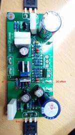
Soo.. mods are done. The good news first, the 100ohm potentiometer worked perfectly to adjust the dc offset. It seemed to drift a bit with temp, but just around 10mV.
The bad news is that one channel put out a constant DC of maybe 15V.. I double checked my mod, but it was ok, so maybe one of the fets has been damaged when I was drilling, soldering and cutting traces.. I took out the fets for the input stage current source to drill and cut, so maybe one of them got some static.
I'm not sure how to easily check a fet for damage?
I know how to check a std transistor, but I'm not sure if there is a standard failure mode on fet's? Guess they can not be checked for hfe with a std multimeter..?
Look up PassDiy and see Fig 18 for test method and static and handling precautions.
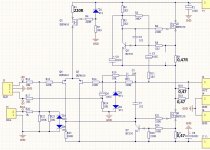
Sometimes a dc offset problem can be addressed by swapping positions for the LTP devices. It could also be the zener diode reference voltage is a bit off the mark - these do come with different tolerances B suffix for instance might be +5% - yours is unidentified.
A subtle change in the current passing through whatever that may be - to ground via R7 - can also influence the LTP by altering the gate voltage on the current source MOSFET.
The 100 ohm adjust will reduce dramatically the gain of the differential stage . (20db according to simulator ) . You need to parallel by a pair of 10 ohms .
Quiescent current.
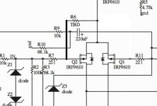
Aleph amps use sense resistor R9 0.47 ohms to fix the quiescent current about 1.27A . Your amp has 0.15 ohms to fix it at 4A. This is the reason of offset which balances the lower stage to much higher current than it is adjusted by the input CCS.
Aleph amps use sense resistor R9 0.47 ohms to fix the quiescent current about 1.27A . Your amp has 0.15 ohms to fix it at 4A. This is the reason of offset which balances the lower stage to much higher current than it is adjusted by the input CCS.

Thank you for your help! Sadly, the schematic is not correct..
I made some corrections on values I measured while fault tracing (might be some errors still).
When I feed it +-14V (desk setup) I have just over 1,5A current. I guess it will be the same current with the 18V supplies too (current seems stable when I vary the voltage a bit).
I found that D1 was missing it's ground reference via R7, so now it seems to work again. Maybe as you say, there is some other fault in the component values giving me the offset. If the amp is low on gain with resistors on the input stage(or maybe in general, since there seem to be few stages?), I guess I could actually make the sound worse by decreasing the open loop gain with the resistors/potentiometer and decreasing feedback correction?
I have not yet added the 10ohm resistors. I'm thinking maybe it's better to skip the resistors all together and maybe find the real cause of the offset? Or just live with it..
Attachments
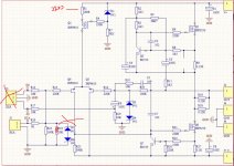
I searched a little bit on Aleph-M(ini) and found another schematic which is not the same but similar. (Mini Aleph, some output problem)
However I guess the adjustment points should be the same for bias, offset and AC gain? A bit curious what R6 is for? Adjusting feedback?
-FOund the answer to that too, DC offset. MOhm-range.
However I guess the adjustment points should be the same for bias, offset and AC gain? A bit curious what R6 is for? Adjusting feedback?
-FOund the answer to that too, DC offset. MOhm-range.
Attachments

Last edited:
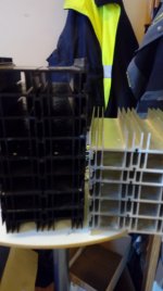
Found some heat sinks in a local scrap yard, I think this should solve the cooling for this and a few other projects 🙂
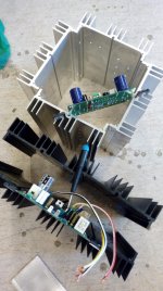
Trying to figure out the layout, I'm leaning towards the two paralleled-option. Should be easier to access for mods etc, if I can just 'fold up' the two halves with all the connectors and wiring going to the rear. I also want to keep the boards close together to minimize ground loop areas, so I don't want to make a normal box with one amp/heat sink on each side.
I think I will need two heat sinks pet channel (one per fet) to keep temps under control without using a fan.
Attachments
I moved the 100ohm potentiometer to the input current source in series with a 175ohm resistor (210 to 275ohm), but that hardly did anything.. I have a feeling it would have to be a lot higher (lower current?) I'm not sure how high I could go here until I start affecting performance of the stage..
Adding R6 between S & G on the inverting input fet, as in the latest schematic, seems like an alternative. Should be better than going with resistors to the rails for PSSR I guess?
I have started to build an enclosure for it. To verify cooling, I tested with one heatsink per FET, and they were only 'warm and cosy' after maybe 30min, so there should be margin to play with the bias later.
Wrote a lot but was automatically logged out before posting.. I will make a short version:
Tried R6 as in the original Aleph schematic, and that made offset worse (more negative), and that makes sense when I think about it since it is the inverting side. So I moved in to the non inverting side, and 700k was not enough. I'm guessing maybe 500k could do it.
Question is if it's bad for the amp performance to put a resistor from current source to the gate of the input fet (non inverting)? Imput impedance will get a little lower, but more?
I'm ignoring the Mohm potetniometer between rails -version, since I can't get one quickly, and would like to assemble the amp in it's new case and test it..
I feel bad about connecting signal path to rails since I imagine it will be bad for PSRR, but maybe that's just me being stupid?
You could move R6 to the negative side.Wrote a lot but was automatically logged out before posting.. I will make a short version:
Tried R6 as in the original Aleph schematic, and that made offset worse (more negative), and that makes sense when I think about it since it is the inverting side. So I moved in to the non inverting side, and 700k was not enough. I'm guessing maybe 500k could do it.
I feel bad about connecting signal path to rails since I imagine it will be bad for PSRR, but maybe that's just me being stupid?
I guess 3M3 ... 4M7 will do. With the ~10k impedance there, no need to worry upsetting the cicuit.
Mona
Attachments

Imbalance of LTP
You might need to change the value of R1 which differs from the usual value of 220R used by Pass but leave this until you look at the LTP gate resistor values connecting to ground and theoretical 0 Volts at the output terminal.
The latter represented by R15 is 100k while the former has R22 with 100k having R23 at 10k in parallel. The combined parallel resistance is 9.09k which is a clear mistake. The divider network of R20 at 1k with 9.09k is going to cause significant attenuation of the input signal of around 11%.
My advice is to undo any changes you have already made and go back to square one.
Then try changing R23 from 10k to 100k - It is conceivable a simple mistake was made with so many 10k and 100k components ending up in confusion.
It might be worth knowing the Pass Aleph 3 LTP gate resistors are 22k at the input to ground and 10k feedback connection to the output.
Attachments
I just tried to remove the 10k resistor on the input, and it did nothing to the offset.. seeing more than 150mV, abt 200 when it gets warm.
I have a potentiometer on the current source resistor (R1), and that is maxed out at 270ohm, if i lower it, the offset goes higher. It was 220 before.
I have a potentiometer on the current source resistor (R1), and that is maxed out at 270ohm, if i lower it, the offset goes higher. It was 220 before.
Last edited:
Time for some more measurements
It is not clear whether or not any suggested networks from the gate of Q5 connecting to the supply rails are still in place.
You have measured R1 which is now a trimmer, I suggest you check R25 by measurement too to make sure the value is 390R.
Then measure the voltage drops across R1 and R25 and deduce the level of current flowing through each of these from Ohms law. Also check the voltage at the bottom end of D1 to see this is the +ve rail voltage less 9V.
For the LTP to balance the current flow in R25 should be roughly half of that flowing through R1.
I just tried to remove the 10k resistor on the input, and it did nothing to the offset.. seeing more than 150mV, abt 200 when it gets warm.
I have a potentiometer on the current source resistor (R1), and that is maxed out at 270ohm, if i lower it, the offset goes higher. It was 220 before.
It is not clear whether or not any suggested networks from the gate of Q5 connecting to the supply rails are still in place.
You have measured R1 which is now a trimmer, I suggest you check R25 by measurement too to make sure the value is 390R.
Then measure the voltage drops across R1 and R25 and deduce the level of current flowing through each of these from Ohms law. Also check the voltage at the bottom end of D1 to see this is the +ve rail voltage less 9V.
For the LTP to balance the current flow in R25 should be roughly half of that flowing through R1.
Thank you for taking the time to assist!
I measured R25, and it is 290ohm.I have no other mods in place except the trimmer for the input current source.
Measurements:
R25:388ohm 5,21V 13mA
Zener: 8,91V
R1: 286ohm 13,47V 47mA
Far from 50/50..
I measured R25, and it is 290ohm.I have no other mods in place except the trimmer for the input current source.
Measurements:
R25:388ohm 5,21V 13mA
Zener: 8,91V
R1: 286ohm 13,47V 47mA
Far from 50/50..
Last edited:
I also tried to swap places on Q4/Q5, and the offset is basically the same (-180mV), so it is definitely the circuit, not fet matching..
I don't understand how the input circuit can be in balance since there is a resistor on only one of them?
Could some imbalance in the output stage also be 'pulling it out of balance'? Just wild guesses..
I don't understand how the input circuit can be in balance since there is a resistor on only one of them?
Could some imbalance in the output stage also be 'pulling it out of balance'? Just wild guesses..
Last edited:
- Home
- Amplifiers
- Solid State
- Zerozone class A dc offset adjustment?