I took what I had at hand and what was lying around and build a very preliminary prototype of the amp.
Missing the input transformer I took bobo1on1’s schematic, two power supplies, one for the 12V, one for the bias voltage.
Power supplies are limited at 30V/3A.
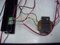
I used an 100V transformer from a peavey amp as output, the headphone output from the cd player as input.
I have no idea what the connections from that transformer are. I’ve got four wires at each side, both sides split.
I connected the power ground to the center tap.
Mosfets are IRFP240, remains from my Aleph-X.
So, one monoblock is working, playing music.
Again, for those who remember, Tori Amos is the lady in charge
There is some hum from ground loops.
As Susan states, an input transformers would probably solve that problem.
I used my headphones and switched between the output of the cd player and the amp’s output to hear the difference.
It’s very hard to tell because the player’s output is stereo, the amp is mono.
So I will not come to any conclusion for now, the thing is just too crappy.
One thing is sure: As long as I keep the bias in control so my second power supplies doesn’t run out of current it seems to have a very smooth and detailed sound.
This is a very nice little amp to build, and because of it’s simplicity has lots of possibilities to test and improve on the very few components.
Thanks again Susan, for such a nice project.
/Hugo 🙂
Missing the input transformer I took bobo1on1’s schematic, two power supplies, one for the 12V, one for the bias voltage.
Power supplies are limited at 30V/3A.
I used an 100V transformer from a peavey amp as output, the headphone output from the cd player as input.
I have no idea what the connections from that transformer are. I’ve got four wires at each side, both sides split.
I connected the power ground to the center tap.
Mosfets are IRFP240, remains from my Aleph-X.
So, one monoblock is working, playing music.
Again, for those who remember, Tori Amos is the lady in charge
There is some hum from ground loops.
As Susan states, an input transformers would probably solve that problem.
I used my headphones and switched between the output of the cd player and the amp’s output to hear the difference.
It’s very hard to tell because the player’s output is stereo, the amp is mono.
So I will not come to any conclusion for now, the thing is just too crappy.
One thing is sure: As long as I keep the bias in control so my second power supplies doesn’t run out of current it seems to have a very smooth and detailed sound.
This is a very nice little amp to build, and because of it’s simplicity has lots of possibilities to test and improve on the very few components.
Thanks again Susan, for such a nice project.
/Hugo 🙂
Attachments
I took some probes away from their measuring points and now the amp is dead quiet. No hum, no noise, nothing.
Tomorrow I'll do the square wave test 😎
/Hugo 🙂
Tomorrow I'll do the square wave test 😎
/Hugo 🙂
Respectable Comments
Hi SUSAN
I have a protection system employed with LDR and Led + zener combination which limits the drive to the gates of mosfet to aroun 12V.
Secondly i dont wind Trafos Myself, A Friend of mine is in this Business to help me.
Some odd Harmonic content is present indeed but its a pleasurable experience although like valve amps.
with Regards
Workhorse Technologies.
Susan-Parker said:Hi amp_man_1,
Thank you for the further information.
Sounds like you are making good progress and the power output looks very impressive 🙂
The protection zeners need to be rated at high enough power that they can sink whatever the input transformer is able to drive into them under overdriven conditions.
I am sure you have already taken this into account but I mention this as your 50VA toroid can potentially shovel a lot of current 🙂
Are you winding the toroids yourself?
Any test results?
Best wishes,
Susan.
Hi SUSAN
I have a protection system employed with LDR and Led + zener combination which limits the drive to the gates of mosfet to aroun 12V.
Secondly i dont wind Trafos Myself, A Friend of mine is in this Business to help me.
Some odd Harmonic content is present indeed but its a pleasurable experience although like valve amps.
with Regards
Workhorse Technologies.
Hi Everyone 🙂
With the two toroids I mentioned last night:
30 VA, Pri single 240 : Sec 15 + 15 volts at 1 amp
217 VA, Pri 120 + 120 : Sec 31 + 31 volts at 3.5 amp
I slung this amp together this morning.
Other parts are:
2 off IRFP140s
Computer CPU heatsink (with fan but that isn't running).
Vreg for Vbias + twiddle pot.
Rterm is 3.7K - 2 off 1K8 with a 100R trip pot in the middle to set balance as the input transformer is not center taped.
2 off 0.47 caps for smoothing of Vsupply and Vbias.
Bias is set low at circa 15 mV on the mosfet source as the heatsink is small (distortion is a bit higher because of this).
I would recommend a bigger heatsink and higher bias level - but this was built from "bits to hand" rather than specially made/wound transformers.
If I was buying the bits in I might go for a 20VA toroid for the input transformer with 2 off 12 volt secondaries (which are primaries in this amp).
Low level bandwidth is 10Hz to 24 kHz (-3 dB), 28 kHz (-6dB).
I am driving the amp from my computer's CD-ROM headphone output, using the two 15 volt secondaries one for each channel.
Power is from a bench PSU using a 30 volt 500 mA power supply (which has current limiting and a meter).
(Now listening to Hazel O'Connor "Breaking Glass".)
With a small bookshelf speaker (TDL Nucleus 1) the volume is fine for personal listening.
For full power I might use the secondaries in series and a proper line driver (e.g. Per-Anders' QRV-07 headphone amp http://home.swipnet.se/~w-50719/hifi/qrv07/index.html ).
The 30VA toroid with 3.7K Rterm has an input impedance (series connection) of 80 ohms.
For anyone who might now be interested in reaching for her/his soldering iron example transformer part numbers from Maplin are:
# N07BA Toroid, 225VA 2 x 35V, UKP 22.99 each
# N91AZ Toroid, 30VA 2 x 12V, UKP 12.99 each
I am sure these can be found cheaper.
This will give a test amp to try out and whilst not as good as using custom transformers should still perform more than adequately and prove the concept.
And if you don't want to keep the amp in this configuration you can always use these toroids in power supplies for your other projects.
Okay 🙂
Best wishes,
Susan.
With the two toroids I mentioned last night:
30 VA, Pri single 240 : Sec 15 + 15 volts at 1 amp
217 VA, Pri 120 + 120 : Sec 31 + 31 volts at 3.5 amp
I slung this amp together this morning.
An externally hosted image should be here but it was not working when we last tested it.
Other parts are:
2 off IRFP140s
Computer CPU heatsink (with fan but that isn't running).
Vreg for Vbias + twiddle pot.
Rterm is 3.7K - 2 off 1K8 with a 100R trip pot in the middle to set balance as the input transformer is not center taped.
2 off 0.47 caps for smoothing of Vsupply and Vbias.
Bias is set low at circa 15 mV on the mosfet source as the heatsink is small (distortion is a bit higher because of this).
I would recommend a bigger heatsink and higher bias level - but this was built from "bits to hand" rather than specially made/wound transformers.
If I was buying the bits in I might go for a 20VA toroid for the input transformer with 2 off 12 volt secondaries (which are primaries in this amp).
Low level bandwidth is 10Hz to 24 kHz (-3 dB), 28 kHz (-6dB).
I am driving the amp from my computer's CD-ROM headphone output, using the two 15 volt secondaries one for each channel.
Power is from a bench PSU using a 30 volt 500 mA power supply (which has current limiting and a meter).
(Now listening to Hazel O'Connor "Breaking Glass".)
With a small bookshelf speaker (TDL Nucleus 1) the volume is fine for personal listening.
For full power I might use the secondaries in series and a proper line driver (e.g. Per-Anders' QRV-07 headphone amp http://home.swipnet.se/~w-50719/hifi/qrv07/index.html ).
The 30VA toroid with 3.7K Rterm has an input impedance (series connection) of 80 ohms.
For anyone who might now be interested in reaching for her/his soldering iron example transformer part numbers from Maplin are:
# N07BA Toroid, 225VA 2 x 35V, UKP 22.99 each
# N91AZ Toroid, 30VA 2 x 12V, UKP 12.99 each
I am sure these can be found cheaper.
This will give a test amp to try out and whilst not as good as using custom transformers should still perform more than adequately and prove the concept.
And if you don't want to keep the amp in this configuration you can always use these toroids in power supplies for your other projects.
Okay 🙂
Best wishes,
Susan.
Hi Hugo,
Very pleasing to see your progress.
The amp in itself should be absolutely quiet with no hiss, hum or other noises.
I don't know what the thermal noise of a power mosfet is in this configuration however I recall testing full power sine wave versus open input and got over 130 dB but that was a long time ago.
Looking forward to the results of this (will depend a lot on the headphone amp that is driving the input).
Very encouraging - see what I was prompted to try out this morning 🙂
Best wishes,
Susan.
Very pleasing to see your progress.
Netlist said:I took some probes away from their measuring points and now the amp is dead quiet. No hum, no noise, nothing.
Tomorrow I'll do the square wave test 😎
/Hugo 🙂
The amp in itself should be absolutely quiet with no hiss, hum or other noises.
I don't know what the thermal noise of a power mosfet is in this configuration however I recall testing full power sine wave versus open input and got over 130 dB but that was a long time ago.
Looking forward to the results of this (will depend a lot on the headphone amp that is driving the input).
Very encouraging - see what I was prompted to try out this morning 🙂
Best wishes,
Susan.
Re: Respectable Comments
Hi amp_man_1,
Thanks for the further info.
I was sure you would have already had something in place for the protection as you seem well experienced in high power mosfet amps already.
I would guess your 50VA input transformer is starting to drop around 20 kHz?
Matching the mosfets should help with the harmonics, as will custom winding a bifilar output transformer if you haven't already done that.
For the output transformer one needs to be quite generous with the core size as toroids have a sharper saturation knee than standard EI lamination transformers and this will affect performance at higher powers.
Also try adjusting the bias level when the amp is running at the "normal" power output you would be using.
Great 🙂
Best wishes,
Susan.
Hi amp_man_1,
Thanks for the further info.
amp_man_1 said:Hi SUSAN
I have a protection system employed with LDR and Led + zener combination which limits the drive to the gates of mosfet to aroun 12V.
Secondly i dont wind Trafos Myself, A Friend of mine is in this Business to help me.
Some odd Harmonic content is present indeed but its a pleasurable experience although like valve amps.
with Regards
Workhorse Technologies.
I was sure you would have already had something in place for the protection as you seem well experienced in high power mosfet amps already.
I would guess your 50VA input transformer is starting to drop around 20 kHz?
Matching the mosfets should help with the harmonics, as will custom winding a bifilar output transformer if you haven't already done that.
For the output transformer one needs to be quite generous with the core size as toroids have a sharper saturation knee than standard EI lamination transformers and this will affect performance at higher powers.
Also try adjusting the bias level when the amp is running at the "normal" power output you would be using.
Great 🙂
Best wishes,
Susan.
Re: Re: Respectable Comments
ThanX Susan For Information Regarding Harmonic generation.
We will surely get something from it.
The transformer for output is rated at 500VA and the winding is interleaved Quad Bifillar.
With Regards
Workhorse Technologies.
Susan-Parker said:Hi amp_man_1,
Thanks for the further info.
I was sure you would have already had something in place for the protection as you seem well experienced in high power mosfet amps already.
I would guess your 50VA input transformer is starting to drop around 20 kHz?
Matching the mosfets should help with the harmonics, as will custom winding a bifilar output transformer if you haven't already done that.
For the output transformer one needs to be quite generous with the core size as toroids have a sharper saturation knee than standard EI lamination transformers and this will affect performance at higher powers.
Also try adjusting the bias level when the amp is running at the "normal" power output you would be using.
Great 🙂
Best wishes,
Susan.
ThanX Susan For Information Regarding Harmonic generation.
We will surely get something from it.
The transformer for output is rated at 500VA and the winding is interleaved Quad Bifillar.
With Regards
Workhorse Technologies.
Amp-Man
How does it compare to class D amps that you are involved in.? Did you put together a UCD module? How does zero impedance amp compare to this?
JOhn
How does it compare to class D amps that you are involved in.? Did you put together a UCD module? How does zero impedance amp compare to this?
JOhn
Susan-Parker said:Hi bobo1on1,
I have dug around and unearthed the two closest toroids that I have, unfortunately not very close to the ones you are thinking about:
30 VA, 15 + 15 volts at 1 amp
31.5 mH at 1kHz, 1.2 K ohm
273 mH at 120 Hz, 620 ohm
217 VA, 31 + 31 volts at 3.5 amp
95 mH at 1 kHz, 1.77k ohm
541 mH at 120 Hz, 922 ohm
So reading between the lines, looking to see which way the wind is blowing and checking on the phase of the Moon my answer is:
If you are more interested in hi end response and not so worried about bass, then go for the 2x24 volts.
If you want the bass and are not so worried about the high end then the extra inductance of the 2x35 will help.
It is difficult to make any better judgments as much depends on the inductance, core quality/material, windings, etc.
I hope this helps.
Best wishes,
Susan.
Thanks for the measurements, I have been using a 2x 12 volts EI transformer for a while an it sounds fine to my opinion, although I don't have any measuring equipment, even my multimeter is broke 😀
I think I'll go with the 2x24 volts, with no input transformers the bass sounds fine to me.
Too bad I don't have any specifications of the transformers, all I know is they are very cheap, so probably really old or used but that shoudn't matter as toroids can last a long time.
jkeny said:Amp-Man
How does it compare to class D amps that you are involved in.? Did you put together a UCD module? How does zero impedance amp compare to this?
JOhn
HI JOHN
Some facts
Our regular production is High power greater than 1000WRMS N-Channel Mosfet amps
We are doing R & D into CLASS-D in BD modulation Mode
Designed Some Prototypes on Class-D but Still Improving.
Also Built Zero impedance Susan's amp only to satisfy our quench for amplifier designing.
Our Class-D amps are Clocked Type and not of Self-oscillating type as UCD.
Secondly , When we compare the sound of the Susan's amp with Class-D of our design, there r following differences.
Class-D Exhibits very Lower ODD Harmonics than ZF amp
While on other hand odd harmonics are pleasing to hear.
Heat dissipiation is very less than ZF amp.
The main difference between our Class-D and ZF amp is simplicity of ZF amp and complexity of Class-D.
At last our Designed class-D is in no way inferior to our other Class-Ab designs.
The ZF amp of Susan is very simple high Quality Pleasing sounded meant for only Domestic Audiophile DIYER type users, While our design caters high-end Professional users .
with Regards
Workhorse Technologies
Hi everyone,
I have been listening to several CDs during the afternoon on the Toroid amplifier, and despite being mono, must say that I feel quite up beat - being reminded of the reasons and enthusiasm that made me start doing this project in the first place.
I am currently listening to Euphoria (TTVCD3007)
http://www.discogs.com/release/85903
... and the amp, even on a measly 500 mA, is really kicking the bass out.
Perhaps unsurprisingly I am now running the heatsink fan off the 7812 regulator. I will probably change to a 7808 for this. Running slowly it shouldn't add any noise to that which my computer makes (noisy beast).
The bench PSU's meter set to current makes a good VU substitute (then I can ignore the twenty volts ripple on the supply when the bass hits).
Anyway, I will have to say that I have had to re-evaluate my thoughts about toroids.
They may not give the finesse or the bandwidth of the EI transformers, but listening to what is essentially a reconfigured mains power supply is very gratifying. And given that the amp is being driven by a cheepie computer CD-ROM headphone amp the sound is very good.
Best wishes,
Susan.
Susan-Parker said:Hi everyone,
Anyway, I will have to say that I have had to re-evaluate my thoughts about toroids.
They may not give the finesse or the bandwidth of the EI transformers, but listening to what is essentially a reconfigured mains power supply is very gratifying. And given that the amp is being driven by a cheepie computer CD-ROM headphone amp the sound is very good.
Best wishes,
Susan.
Hi Susan,
WRT Toroids vs E-I:
E-I have far less bandwidth than toroids.
Cheers,
Terry
Terry_Demol said:E-I have far less bandwidth than toroids.
That's because E-I has an airgap but EI does not. 😉 Just kidding.
It would be interesting to compare an EI with a toroid that has the same leakage reactance. With the primary and secondary wound over the whole length of the core instead of being "bunched up" like in an EI, the primary and secondary would be more tightly coupled I expect, leading to a better HF response.
Susan
As mentioned above, most toroidal mains transformers I've measured have very high bandwidth, in the order of 100's of kHz.
EI types usually have less, although it depends upon the winding technique used, split bobbin have the lowest bandwidth, for the obvious reasons.
Andy.
As mentioned above, most toroidal mains transformers I've measured have very high bandwidth, in the order of 100's of kHz.
EI types usually have less, although it depends upon the winding technique used, split bobbin have the lowest bandwidth, for the obvious reasons.
Andy.
All transformers show great bandwidth when they are driven from a low impedance soruce and loaded with a high impedance load
To do useful bandwith tests, you have to use a known source impedance and a known load impedance. If you are testing transformers for a certain application, try to use impedances close to the actual working values
To do useful bandwith tests, you have to use a known source impedance and a known load impedance. If you are testing transformers for a certain application, try to use impedances close to the actual working values

Re: Susan
Hi Everyone,
Thank you for your further comments.
I have ordered a 15VA toroid to try out for the input transformer with 2 off 12 volt secondaries (which are primaries in this amp).
I paid the extra couple of bucks (see, no expense spared for the DIYaudio listees) for the version with dual 115 primaries as this is the type people with 120 vac will need to get to have the same set up as myself.
Due to the way the transformer is likely to have been wound I am not expecting to use this as a center tap, but will check.
I am hoping that this transformer will go up a bit higher than the 30VA's 24 kHz, but life is full of surprises so I only ordered on to try. If it does the business I will get a second one.
It will probably arrive on Thursday.
Doing some further research it would appear that toroid manufacturers now often wind the secondaries bi-filar to get good matching. This would explain the better than expected results from the test amp.
When I originally was doing this design work ten years ago it was hard enough getting a regular EI transformer multi-filar wound. The toroid capable manufacturer couldn't (or wouldn't) do it and insisted on their own multi-section winding regime - and surprise surprise, they didn't work.
At the time I didn't feel up to threading a large toroid myself, however as I still have two large (circa 500VA) toroids that only go up to 10 kHz I guess it's getting close to the time to strip them down and rewind them.
Best wishes,
Susan.
I dug through my stuff this evening and pulled out a couple of 115V to 15-0-15V and 115V to 44-0-44 toroids. The 15V guys are probably around 20-30VA, and I'm going to try and use them as input transformers following a capacitor coupled Class A JFET or MOSFET follower. I'll start out using a couple of PN4393s in "FETWhite" configuration, as I have plenty around, and this JFET has pretty reasonable specs for gain, noise, and output current capability( much higher IDSS than the 2SK170, even with the V ranking). The 44V transformers will serve as outputs, as they look to be good for a few hundred VA. I'll probably start by matching up some IRF540s and use a smalller MOSFET driven by a current source for the bias, mounted on the same heat sink as the outputs for bias tracking. I'm really curious to see what quality I can squeeze out of the stock toroidal transformers. It looks like both transformers will give me an effective voltage gain of about 20, which will be good enough to drive with my stock preamp. My speakers are pretty sensitive, so I don't anticipate a lot of problems driving them to a reasonable volume level. Since I just picked up a nice DC current probe on Ebay, I can pay special attention to looking for transformer saturation on transients, or with 20Hz square wave excitation. Whether it really works or not, the whole setup should be pretty easy to try, and it sure beats trying to hand-wind everything....
Hi Wrenchone,
Thank you for your post and interest in the amplifier.
I have made a few comments which I am sure you are already up to speed on but hopefully will be relevant to others following this thread.
Can you see if the 44V windings on the big toroid look to be bifilar wound?
Remember with the IRF540's the 100 volt Drain to Source Breakdown Voltage rating and that the output transformer generates the negative rail so you will want a power supply of under 50 volts DC - circa 45 max off load to allow for line voltage fluctuation.
I would recommend that you also use a IRF540 for the bias generation, and you run about 100 mA current through it. I use Schottky power diodes to give me the extra voltage offset for the bias to the driving IRF540s. This will most accurately track the temperature changes.
Using a 78xx voltage regulator in constant current mode - also bolted to the heatsink - gives you a thermal shutdown if everything does get too hot. (But limits the supply to 35 volts max.)
Also use this 100 mA current source to match up the IRF540s by connecting the mosfet's source to ground and the gate and drain together to the current source. Then measure the resultant voltage across the device. (I made up a test jig with crock clips.)
In the picture of my toroid test amp there is a third IRFP140 lurking in the middle of the heatsink which is generating a tracking bias voltage.
I haven't mentioned this in the past because I didn't want to over complicate things.
If you parallel up IRF540s you will need to add low value resistors (circa 0.47 ohm?) between the sources and the common point on the transformer - as per standard mosfet amp practice else one device will current hog.
Note: With a 35 volt power supply and an 8 ohm load with a full amplitude sine wave drive to the output mosfets you could hit 200 watts plus.
(If you have sensitive speakers you might want to run initially from a somewhat lower voltage.)
NOTE: Although my concept schematic in the Zeus page shows the zener directly across the mosfet source to gate the IR application notes says that the gate end of the zener should be the other side of the gate resistor otherwise there is a possibility of HF oscillation.
If my test amp is anything to go by you should have lots of power.
However don't be surprised if the measured distortion levels are up to the 1% mark in places as you are running across what are in my amp the transformer primaries.
With my quad-filar would output transformer I am at 2:1 into 8 ohms. If I raise the load impedance to 12 or 16 ohms the distortion drops dramatically. Hence my preference to use a full transformer here.
However this way does get one up and running quickly.
This would be very interesting as toroids have a much sharper saturation knee curve. If the output transformer saturates the current in the driving mosfet will rise quickly - hence the use of a fuse AFTER the supply capacitor.
Use of a square wave for testing should be done with an edge slew rate that is appropriate to the bandwidth of the amplifier, not at several hundred megahertz equivalent speed.
So if the input transformer has a -3 dB point of 50 kHz the rise/fall time (10% to 90% level transition) of the square wave edge should be no less than 20 uS.
Indeed it does.
And it gets one going on a bench test that allows experimentation and an initial appraisal of the sound. If one likes what one is hearing, then one can refine the transformers, even to the point of winding ones own.
General Note to ALL.
I have approached a toroid manufacturer who has experience with audio toroids with a view to see if they would supply transformers for this project. Initial response seems encouraging and I will let you know when I have any firm information.
However looking through their price list be warned that a full set of 2 input, 2 output and a PSU toroid will be USD 1000 minimum.
Sowter on the other hand are a lot less expensive, and I have asked them to quote for the 50 watt quad filar output transformer (with split secondaries).
Best wishes,
Susan.
http://www.susan-parker.co.uk/zeus.htm
Thank you for your post and interest in the amplifier.
I have made a few comments which I am sure you are already up to speed on but hopefully will be relevant to others following this thread.
wrenchone said:I dug through my stuff this evening and pulled out a couple of 115V to 15-0-15V and 115V to 44-0-44 toroids. The 15V guys are probably around 20-30VA, and I'm going to try and use them as input transformers following a capacitor coupled Class A JFET or MOSFET follower. I'll start out using a couple of PN4393s in "FETWhite" configuration, as I have plenty around, and this JFET has pretty reasonable specs for gain, noise, and output current capability( much higher IDSS than the 2SK170, even with the V ranking). The 44V transformers will serve as outputs, as they look to be good for a few hundred VA.
Can you see if the 44V windings on the big toroid look to be bifilar wound?
I'll probably start by matching up some IRF540s and use a smaller MOSFET driven by a current source for the bias, mounted on the same heat sink as the outputs for bias tracking.
Remember with the IRF540's the 100 volt Drain to Source Breakdown Voltage rating and that the output transformer generates the negative rail so you will want a power supply of under 50 volts DC - circa 45 max off load to allow for line voltage fluctuation.
I would recommend that you also use a IRF540 for the bias generation, and you run about 100 mA current through it. I use Schottky power diodes to give me the extra voltage offset for the bias to the driving IRF540s. This will most accurately track the temperature changes.
Using a 78xx voltage regulator in constant current mode - also bolted to the heatsink - gives you a thermal shutdown if everything does get too hot. (But limits the supply to 35 volts max.)
Also use this 100 mA current source to match up the IRF540s by connecting the mosfet's source to ground and the gate and drain together to the current source. Then measure the resultant voltage across the device. (I made up a test jig with crock clips.)
In the picture of my toroid test amp there is a third IRFP140 lurking in the middle of the heatsink which is generating a tracking bias voltage.
I haven't mentioned this in the past because I didn't want to over complicate things.
If you parallel up IRF540s you will need to add low value resistors (circa 0.47 ohm?) between the sources and the common point on the transformer - as per standard mosfet amp practice else one device will current hog.
Note: With a 35 volt power supply and an 8 ohm load with a full amplitude sine wave drive to the output mosfets you could hit 200 watts plus.
(If you have sensitive speakers you might want to run initially from a somewhat lower voltage.)
NOTE: Although my concept schematic in the Zeus page shows the zener directly across the mosfet source to gate the IR application notes says that the gate end of the zener should be the other side of the gate resistor otherwise there is a possibility of HF oscillation.
I'm really curious to see what quality I can squeeze out of the stock toroidal transformers. It looks like both transformers will give me an effective voltage gain of about 20, which will be good enough to drive with my stock preamp. My speakers are pretty sensitive, so I don't anticipate a lot of problems driving them to a reasonable volume level.
If my test amp is anything to go by you should have lots of power.
However don't be surprised if the measured distortion levels are up to the 1% mark in places as you are running across what are in my amp the transformer primaries.
With my quad-filar would output transformer I am at 2:1 into 8 ohms. If I raise the load impedance to 12 or 16 ohms the distortion drops dramatically. Hence my preference to use a full transformer here.
However this way does get one up and running quickly.
Since I just picked up a nice DC current probe on Ebay, I can pay special attention to looking for transformer saturation on transients, or with 20Hz square wave excitation.
This would be very interesting as toroids have a much sharper saturation knee curve. If the output transformer saturates the current in the driving mosfet will rise quickly - hence the use of a fuse AFTER the supply capacitor.
Use of a square wave for testing should be done with an edge slew rate that is appropriate to the bandwidth of the amplifier, not at several hundred megahertz equivalent speed.
So if the input transformer has a -3 dB point of 50 kHz the rise/fall time (10% to 90% level transition) of the square wave edge should be no less than 20 uS.
Whether it really works or not, the whole setup should be pretty easy to try, and it sure beats trying to hand-wind everything....
Indeed it does.
And it gets one going on a bench test that allows experimentation and an initial appraisal of the sound. If one likes what one is hearing, then one can refine the transformers, even to the point of winding ones own.
General Note to ALL.
I have approached a toroid manufacturer who has experience with audio toroids with a view to see if they would supply transformers for this project. Initial response seems encouraging and I will let you know when I have any firm information.
However looking through their price list be warned that a full set of 2 input, 2 output and a PSU toroid will be USD 1000 minimum.
Sowter on the other hand are a lot less expensive, and I have asked them to quote for the 50 watt quad filar output transformer (with split secondaries).
Best wishes,
Susan.
http://www.susan-parker.co.uk/zeus.htm
When I do this sort of threshold voltage matching I find it useful to lay all the prospective mosfets side by side on a thick slab of metal. This ensures that the mosfet teperature does not change appreciably during the measurement and that all the mosfets are at the same temp.Susan-Parker said:Also use this 100 mA current source to match up the IRF540s by connecting the mosfet's source to ground and the gate and drain together to the current source. Then measure the resultant voltage across the device. (I made up a test jig with crock clips.)
- Home
- Amplifiers
- Solid State
- Zero Feedback Impedance Amplifiers