3D additive printing of Titanium
Not a problem any more as titanium can be 3D additive printed 🙂
3D Printing Service i.materialise
Guess what I am thinking of using for my tone arm A frame structure?
Best wishes,
Susan.
Hi,
for instance, drilling titanium can be a little bit tricky if you are unaccustomed to it and you need to sharpen frequently...
😀
Not a problem any more as titanium can be 3D additive printed 🙂
3D Printing Service i.materialise
Guess what I am thinking of using for my tone arm A frame structure?
Best wishes,
Susan.
Hi Patrick,
Thank you for your thoughts.
I am okay (although I have been finding work quite stressful).
Hopefully you are keeping well.
Best wishes,
Susan.
Dear Susan,
Hope all is well.
Best wishes,
Patrick
Thank you for your thoughts.
I am okay (although I have been finding work quite stressful).
Hopefully you are keeping well.
Best wishes,
Susan.
IXTH20N50D mosfets
Hi,
Quick update to let you know that I am progressing this. They are available, but there is a MOQ of 60 pieces. I am waiting to receive a proper quote, should be next week.
Thanks.
Best wishes,
Susan.
Hi,
Susan,
Can you advise where I can get IXTH20N50D mosfets? Do you have any for I can purchase from you?
Quick update to let you know that I am progressing this. They are available, but there is a MOQ of 60 pieces. I am waiting to receive a proper quote, should be next week.
Thanks.
Best wishes,
Susan.
Hi Joao,
To be biased, I think mine is better. But that is my preference and given that I have now been working on my transformer based follower amplification topology for the best part of two decades, probably my operant conditioning too.
Amongst other things in my topology the follower has below unity gain, therefore variations in load impedance etc. do not cause problems in the way a common source voltage amplifier does.
Also, unless one sets up as near identical circuits as possible, with mosfets, transformers and base topology (SE or PP) staying the same in both, one can't really make the absolute comparison between the two.
With mine, the low level "first watt" distortion is down at 0.005% THD for the whole amplifier i.e. pre and power stages (in 4:1 mode which is how I have my system setup). And that is without any global or local looped feedback, just the degenerative action of the followers.
Without naming names, someone who has been very active in the HiFi business (actually selling stuff for many years) told me recently that my system was the best solid state system he had ever heard. That was in his listening room, with his speakers, his normal CD player and his selection of music (although he did suffer to listen to a few of my fave tracks too).
Of course, this is all anecdotal, and at the end of the day the main attribute of any audio system is that you like to listen to it and can enjoy the music without being distracted by the sound quality or other artefacts.
The map is not the territory as one might say.
Best wishes,
Susan.
Hello Susan
thanks for the response. Yes I tried out your follower technology as a single ended line stage and it sounded pretty good 🙂
Do you have experience in using it for a phono stage? I think the problem is the step-up ratio of the transformer, and second the quantity of stages when using an LCR-RIAA and a low output impedance of 600 ohms.
Phono preamps
The step up ratios for such a large amount (and my cartridge is low output about 250 uV) would really push it.
Whilst I am going to look at this option once I have the phono stage a bit further along for the time being I am planning to use C3g tubes triode strapped for the gain as a first step. I have bench tested the individual stages, now I just have to build the thing.
And yes, I have a box of C3gs to hand as they are very shiny (and individually serial numbered).
Still manage to use four transformers pre channel though, so I am not moving away too far from my comfort zone.
I have two intermediate passive filter stages, as I am going to set up to be able to equalise for non RIAA discs as well (and yes, even I with my small record collection still manage to have a number or pre-RIAA examples).
Output is designed for 10K load, i.e. into my transformer pre.
And the power supply uses a Zeus output stage topology in step up running at 40 to 50 kHz for the B supply HT.
Please appreciate that this side of things is still very much in the early development stage, with most of the design still very fluid. So I can't really give much more info as I am still working it out for myself 🙂
Best wishes,
Susan.
Hello Susan
Do you have experience in using it for a phono stage? I think the problem is the step-up ratio of the transformer, and second the quantity of stages when using an LCR-RIAA and a low output impedance of 600 ohms.
The step up ratios for such a large amount (and my cartridge is low output about 250 uV) would really push it.
Whilst I am going to look at this option once I have the phono stage a bit further along for the time being I am planning to use C3g tubes triode strapped for the gain as a first step. I have bench tested the individual stages, now I just have to build the thing.
And yes, I have a box of C3gs to hand as they are very shiny (and individually serial numbered).
Still manage to use four transformers pre channel though, so I am not moving away too far from my comfort zone.
I have two intermediate passive filter stages, as I am going to set up to be able to equalise for non RIAA discs as well (and yes, even I with my small record collection still manage to have a number or pre-RIAA examples).
Output is designed for 10K load, i.e. into my transformer pre.
And the power supply uses a Zeus output stage topology in step up running at 40 to 50 kHz for the B supply HT.
Please appreciate that this side of things is still very much in the early development stage, with most of the design still very fluid. So I can't really give much more info as I am still working it out for myself 🙂
Best wishes,
Susan.
Hi Susan,
I just was fooling around...anyway, maybe Selective Laser Sintering is the right way to go.
I just was fooling around...anyway, maybe Selective Laser Sintering is the right way to go.
The step up ratios for such a large amount (and my cartridge is low output about 250 uV) would really push it.
Whilst I am going to look at this option once I have the phono stage a bit further along for the time being I am planning to use C3g tubes triode strapped for the gain as a first step. I have bench tested the individual stages, now I just have to build the thing.
And yes, I have a box of C3gs to hand as they are very shiny (and individually serial numbered).
Still manage to use four transformers pre channel though, so I am not moving away too far from my comfort zone.
I have two intermediate passive filter stages, as I am going to set up to be able to equalise for non RIAA discs as well (and yes, even I with my small record collection still manage to have a number or pre-RIAA examples).
Output is designed for 10K load, i.e. into my transformer pre.
And the power supply uses a Zeus output stage topology in step up running at 40 to 50 kHz for the B supply HT.
Please appreciate that this side of things is still very much in the early development stage, with most of the design still very fluid. So I can't really give much more info as I am still working it out for myself 🙂
Best wishes,
Susan.
Susan
we both use transformer coupling and let's assume that we use a step-up transformer for MC-carts, so we can calculate with around 4mV input signal for the MM phono stage.
I'd like to share some experiences regarding your phono stage because I designed already a transformer coupled too. Good base but let me recommend to use a D3a or similar tube because of microphonics. If you will keep the C3g ülease don't strip the steel case of the tube because of hum and shielding.
The LCR-RIAA you can do in 2 units as well and calculate for different EQ-curves. Current I plan this as well.
Searching for a new challenge I began to experiment with solid state phono stages - of course transformer coupled. Current I use a transformer coupled JFet phono pre with 600 Ohm LCR-RIAA - using the transformers from the tube preamps it measures quite well:
But I never listened better to my analog records. In short, it beats all my previous designed tube versions - and is still under development. Just curious when I change to the proper transformers 🙂
Regarding the above mentioned input signal and designing a MM phono stage do you think your kind of stages can handle the step-up transformation, for example a 1:10 / 20dB for a stage?
Hi Roscoe,
...
I am prototyping a pair of amorphous C core transformers (waiting on them, probably a few more weeks till they arrive), which will be interesting comparison to the M6 EI laminations. When I get them and have runs some tests I will post up the results.
Hello Susan,
Any news on the results of the amorphous C-core.
I'am trying to work out a configuration to drive my DYI Electrostatic speakers.
Source is a miniDSP, with output impedance of 560 Ohm. This has caused
me a lot of problems to drive a ZEUS stage, but (in simulation) it should work.
Still struggling with some transformer parameters in LTspice for now.
I'll keep you informed about the progress or results,
Edwin
Dear Susan,
Thank you for your reply.
My intention to begin with is to build a single channel only Zeus, as a test bed. My understanding is that I would also need to build a line driver for the Zeus because the input impedance is very low and that the output impedance of most pre-amps is too high to effectively drive the Zeus?
Initially , I'll be using the pr-out section of my Marantz receiver, which has an output voltage of 1.5v and 600 ohms, which is too high to drive the Zeus. I've noticed though, that the tape-out section is 0.18v and 50 ohms - would this be low enough to drive the Zeus effectively without the need of a line driver?
Lots of Thanks,
Peter
Dear Susan,
your amp is similar to this one which has even a lower parts number. It deserves to be built!
your amp is similar to this one which has even a lower parts number. It deserves to be built!
Punch for Portables Amplifier
Hi,
Thanks for that link. The P4P circuit is interesting indeed. I have not seen this article before so appreciate the reference.
The mosfets need gate input protection, hence the additional zener diodes. They are not part of the audio path and only come into play in overdrive conditions to prevent device self-immolation.
With depletion mosfets, one gets auto bias from the transformer DC resistance, so the additional biasing components are not required. Apart from the zeners and gate resistors it has only the two transformers and the two mosfets, all being ground referenced. That gives an overall component count of 8 parts for the power stage.
In the above the biasing is shown as a simple pair of resistors (R1, R2). In this case with a single battery this would be okay, but for better (safer) operation at higher powers one would use stabilised temperature tracking.
I have experimented with NPN bipolars, but get better performance with mosfets. I have not tried using germanium transistors.
With the 2N255 they only have a 35V Vce spec, so one would have to run on a maximum of a nominal 12V supply (i.e. automotive up to 15 would be okay).
Note that I use a step down transformer output, which significantly improves the distortion characteristics for standard impedance loads. So I typically run a supply of 32 to 48 volts (which gives nearly double that as a swing on the output device). Hence the need to use 150V or higher spec'ed parts.
Finally the P4P circuit is a power stage, it still needs a line driver to operate (in this case the transistor radio speaker jack output).
Once again thank you for this reference, appreciated.
Best wishes,
Susan.
Hi,
Thanks for that link. The P4P circuit is interesting indeed. I have not seen this article before so appreciate the reference.
Dear Susan,
your amp is similar to this one which has even a lower parts number. It deserves to be built!
The mosfets need gate input protection, hence the additional zener diodes. They are not part of the audio path and only come into play in overdrive conditions to prevent device self-immolation.
With depletion mosfets, one gets auto bias from the transformer DC resistance, so the additional biasing components are not required. Apart from the zeners and gate resistors it has only the two transformers and the two mosfets, all being ground referenced. That gives an overall component count of 8 parts for the power stage.
In the above the biasing is shown as a simple pair of resistors (R1, R2). In this case with a single battery this would be okay, but for better (safer) operation at higher powers one would use stabilised temperature tracking.
I have experimented with NPN bipolars, but get better performance with mosfets. I have not tried using germanium transistors.
With the 2N255 they only have a 35V Vce spec, so one would have to run on a maximum of a nominal 12V supply (i.e. automotive up to 15 would be okay).
Note that I use a step down transformer output, which significantly improves the distortion characteristics for standard impedance loads. So I typically run a supply of 32 to 48 volts (which gives nearly double that as a swing on the output device). Hence the need to use 150V or higher spec'ed parts.
Finally the P4P circuit is a power stage, it still needs a line driver to operate (in this case the transistor radio speaker jack output).
Once again thank you for this reference, appreciated.
Best wishes,
Susan.
tube amp output transformers
Unfortunately most tube amp transformers have a large ratio step-down as they are designed for tubes in voltage gain mode, so one only gets fractional watts in my follower configuration.
Best wishes,
Susan.
I Bet any old tube amp output transformer would be perferct !
Unfortunately most tube amp transformers have a large ratio step-down as they are designed for tubes in voltage gain mode, so one only gets fractional watts in my follower configuration.
Best wishes,
Susan.
If I convert your topology into a OTL version, I will get a schematic (only buffer) from TCJ Blog 6As requested a seperate thread on transformer based solid state amplifers.
The schematic:

This amplifier is based on Impedance Amplification and has similar distortion characteristics to valve triode designs.
It is relativly easy to build and only has one twiddle pot to set the bias level. The pic shows a monoblock which I built nearly ten years ago and it has not needed adjustment since.
Best wishes, Susan. P.S. Yes, it does work.
about
Circlotron Amplifiers Once Again
respective "simple circlotrom amplifier" about
MOSFET push-pull buffer/amplifier
Simple Circlotron Amplifier (and include front end (LTP/VAS) a schematic like this:
http://www.ne.jp/asahi/evo/amp/J200K1529/exp21.gif)
what are the pros and cons of both (i. e. with and without output transformer) from the audible view (not from the THD/IM measuring results) ??
BTW - here are to find more URL's with additional details arround CSPP/Circlotron topologies:
http://www.diyaudio.com/forums/soli...e-ended-related-solid-state-output-stage.html
http://www.diyaudio.com/forums/soli...better-audio-non-complements-audio-power.html
http://www.diyaudio.com/forums/soli...-names-commercial-solid-state-amplifiers.html
Attachments
Last edited:
Circlotron Zeus
Yes, thanks for this one.
A few years ago I did do some circuit simulation of standard and Circlotron version Zeus power stage. Using the transformer of course.
Please accept my apologies if I am being slow however I don't see the point of the version as you show.
1. The two power supplies won't match unless you balance the caps carefully, so the PSU ripple won't cancel out as well.
2. The biasing arrangement won't track, may again add asymmetric ripple, and will result in poor HF bandwidth.
3. Big good quality electrolytic capacitors are fiendishly expensive, the cost of the power supply has just increased significantly (okay, you have got rid of the cost of the output transformer.)
4a. Using the output transformer one can absolutely guarantee that there is no possibility of ever putting any DC across the speaker.
4b. Also with the PP cancellation one CAN have quite high PSU ripple with little effect. Note that I happily run with only 10,000uF smoothing.
5. Why complicate?
6. Finally, using the Circlotron topology one halves the output swing.
7. Oh yes, there is no longer the output transformer to generate the "phantom" negative rail!
Um... ?
It's been a while since I looked at this, so please excuse me if I am coming across as being a bit vague.
Thank you for your interest.
Best wishes,
Susan.
If I convert your topology into a OTL version, I will get a schematic (only buffer) from TCJ Blog 6
about
Circlotron Amplifiers Once Again
respective "simple circlotrom amplifier" about
MOSFET push-pull buffer/amplifier
Simple Circlotron Amplifier (and include front end (LTP/VAS) a schematic like this:
http://www.ne.jp/asahi/evo/amp/J200K1529/exp21.gif)
what are the pros and cons of both (i. e. with and without output transformer) from the audible view (not from the THD/IM measuring results) ??
BTW - here are to find more URL's with additional details arround CSPP/Circlotron topologies:
http://www.diyaudio.com/forums/soli...e-ended-related-solid-state-output-stage.html
http://www.diyaudio.com/forums/soli...better-audio-non-complements-audio-power.html
http://www.diyaudio.com/forums/soli...-names-commercial-solid-state-amplifiers.html
Yes, thanks for this one.
A few years ago I did do some circuit simulation of standard and Circlotron version Zeus power stage. Using the transformer of course.
Please accept my apologies if I am being slow however I don't see the point of the version as you show.
1. The two power supplies won't match unless you balance the caps carefully, so the PSU ripple won't cancel out as well.
2. The biasing arrangement won't track, may again add asymmetric ripple, and will result in poor HF bandwidth.
3. Big good quality electrolytic capacitors are fiendishly expensive, the cost of the power supply has just increased significantly (okay, you have got rid of the cost of the output transformer.)
4a. Using the output transformer one can absolutely guarantee that there is no possibility of ever putting any DC across the speaker.
4b. Also with the PP cancellation one CAN have quite high PSU ripple with little effect. Note that I happily run with only 10,000uF smoothing.
5. Why complicate?
6. Finally, using the Circlotron topology one halves the output swing.
7. Oh yes, there is no longer the output transformer to generate the "phantom" negative rail!
Um... ?
It's been a while since I looked at this, so please excuse me if I am coming across as being a bit vague.
Thank you for your interest.
Best wishes,
Susan.
Depletion MOSFET Zeus System Audio Path
Dear All,
An up to date schematic using depletion mosfets as a quick overview of the full audio path from line level input to speaker drive:

As biasing is from the DC resistance of the transformer primary windings this really is the full schematic of the system.
For brevity the power supplies are representatively shown as batteries (in practise one would have fuses, switches and the like as well of course), and source selection is omitted.
Q1, Q2 & Q3 are all IXTH20N50D parts.
D1, D2 & D3 are 12V zeners.
R1, R2 & R3 are all 100R resistors.
Q1 operates at c. 500mA bias.
Q2 & Q3 operate at c. 750mA bias per device.
And yes, it is drawn in my new 1920's style with curved corners and hop-overs (I am using small symbols with pass-through pins for these so the schematic is still "live"). 🙂
Best wishes,
Susan.
Dear All,
An up to date schematic using depletion mosfets as a quick overview of the full audio path from line level input to speaker drive:
As biasing is from the DC resistance of the transformer primary windings this really is the full schematic of the system.
For brevity the power supplies are representatively shown as batteries (in practise one would have fuses, switches and the like as well of course), and source selection is omitted.
Q1, Q2 & Q3 are all IXTH20N50D parts.
D1, D2 & D3 are 12V zeners.
R1, R2 & R3 are all 100R resistors.
Q1 operates at c. 500mA bias.
Q2 & Q3 operate at c. 750mA bias per device.
And yes, it is drawn in my new 1920's style with curved corners and hop-overs (I am using small symbols with pass-through pins for these so the schematic is still "live"). 🙂
Best wishes,
Susan.
One Less Transformer?
Susan
If the preamp was in the same box as the power amp would getting rid of T2 and T3 and replacing with a suitable transformer be an option?
Regards
Ejam
Susan
If the preamp was in the same box as the power amp would getting rid of T2 and T3 and replacing with a suitable transformer be an option?
Regards
Ejam
Hi Ejam,
Whilst possible there are still advantages to having them seperate.
Line Transformer:
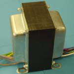
This is single ended and has 500 mA bias current. Hence the size.
Amp Input Transformer:
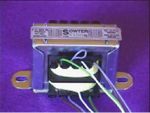
This is way much smaller, and has a simple interleaving S😛:S winding sections per side.
Combining the two and making it as one transformer would significantly increase the complexity and it would be difficult to maintain the bandwidth (as the secondaries would have far higher parasitic capacitence and stuff).
But yes, it could be done.
Personaly I build seperates as I would not be able to physically lift the amp if it was all in one. As it is I find my pre-amp / line-driver a struggle and that has relativly small heatsinks and an external PSU.
Best wishes,
Susan.
Susan
If the preamp was in the same box as the power amp would getting rid of T2 and T3 and replacing with a suitable transformer be an option?
Whilst possible there are still advantages to having them seperate.
Line Transformer:
This is single ended and has 500 mA bias current. Hence the size.
Amp Input Transformer:
This is way much smaller, and has a simple interleaving S😛:S winding sections per side.
Combining the two and making it as one transformer would significantly increase the complexity and it would be difficult to maintain the bandwidth (as the secondaries would have far higher parasitic capacitence and stuff).
But yes, it could be done.
Personaly I build seperates as I would not be able to physically lift the amp if it was all in one. As it is I find my pre-amp / line-driver a struggle and that has relativly small heatsinks and an external PSU.
Best wishes,
Susan.
- Home
- Amplifiers
- Solid State
- Zero Feedback Impedance Amplifiers