Re: Transformer construction
I would have thought that the 2 primaries need winding out of phase other wise you will get 2 positive half cycles out of the secondary ?
The other way is to have the two primaries wired in opposite directions but wind them on in the same phase.
sos said:I'm having a hard time convincing myself that I follow the winding details. Quadfilar is fine, that's not my question.
The 75 W output transformer page says:
"Both sides to have identical number of turns and length of wire i.e. mirror image twins."
Identical number of turns and length makes sense. Mirror image twins to me means that the left side of the bobbin should be wound in one direction and the right side the opposite direction.
I think I'm over interpreting--maybe this isn't what is meant by 'mirror image'. I'm not seeing a big advantage to having two winding directions; I'd appreciate either the details of why it is important or confirmation that it isn't crucial. The single chamber bobbin version of the transformer certainly doesn't do mirror image winding for half the turns!
Another question on the schematic. The transformer has three fat black bars, top, middle and bottom. This is the bobbin, right?
Simple questions,
Thanks,
Steve
I would have thought that the 2 primaries need winding out of phase other wise you will get 2 positive half cycles out of the secondary ?
The other way is to have the two primaries wired in opposite directions but wind them on in the same phase.
Re: Transformer construction
Not really mirror image, and not strictly necessary. You wind both in the same direction. Just makes it easier to connect up if, for instance, the winding are done so that the wires lead out from opposite ends of the bobbin.
Should sound good. Keep in mind, however, that most tube preamps are fairly high output impedance. You want low for this amp.
Sheldon
sos said:The 75 W output transformer page says:
"Both sides to have identical number of turns and length of wire i.e. mirror image twins."
Identical number of turns and length makes sense. Mirror image twins to me means that the left side of the bobbin should be wound in one direction and the right side the opposite direction.
Not really mirror image, and not strictly necessary. You wind both in the same direction. Just makes it easier to connect up if, for instance, the winding are done so that the wires lead out from opposite ends of the bobbin.
jkeny said:hoktuna,
Can you tell how this sounds with a tube preamp - balanced I presume?
Should sound good. Keep in mind, however, that most tube preamps are fairly high output impedance. You want low for this amp.
Sheldon
Re: Re: Transformer construction
I must be missing something--why wouldn't you just pick the primary wires that match in phase, regardless of which way they're wound?
Steve
nigelwright7557 said:
I would have thought that the 2 primaries need winding out of phase other wise you will get 2 positive half cycles out of the secondary ?
The other way is to have the two primaries wired in opposite directions but wind them on in the same phase.
I must be missing something--why wouldn't you just pick the primary wires that match in phase, regardless of which way they're wound?
Steve
Winding thanks
Thanks for the confirmation folks--I'm reading the transformer text much too closely.
Steve
Thanks for the confirmation folks--I'm reading the transformer text much too closely.
Steve
Toroid transformers again
In the zeus topology toroids are used as input step-up or output inductors mainly.
Any major drawbacks to use them as output devices for 1/2 step-down purposes such as for example: a 2x115V centered tapped primary + 2X 55V secondary @ say 2,5A in a mini-zeus linestage?
Has anybody tried this practically?
Thank you.
JC.
Re: Toroid transformers again
The Zeus will require bias current of around an amp. A few percent of that represents tens of milliamps imbalance. Toriods are more sensitive to saturation than EI transformers (which always have a small effective gap), and that is enough to saturate the core of the toroid, and cause distortion to increase. I would think that balancing within a couple of milliamps is going to be impractical. But if you've got one one hand, and a scope, give it a try.
Sheldon
lissitzky said:In the zeus topology toroids are used as input step-up or output inductors mainly.
Any major drawbacks to use them as output devices for 1/2 step-down purposes such as for example: a 2x115V centered tapped primary + 2X 55V secondary @ say 2,5A in a mini-zeus linestage?
Has anybody tried this practically?
Thank you.
JC.
The Zeus will require bias current of around an amp. A few percent of that represents tens of milliamps imbalance. Toriods are more sensitive to saturation than EI transformers (which always have a small effective gap), and that is enough to saturate the core of the toroid, and cause distortion to increase. I would think that balancing within a couple of milliamps is going to be impractical. But if you've got one one hand, and a scope, give it a try.
Sheldon
Re: Toroid transformers again
Thank you Sheldon for the answer. I was not aware that such minute uncanceled DC intensity would cause toroids to saturate. But do you think that such current would be likely to occur with STP55NE06 pairs showing voltage drop differences across Drain-Source of less than 1mV and biased each at 0.25A? Of course slight resistance mismatches of the two transformer primaries might participate in creating the difference but this would apply also for input toroids fed by a DC-free drivers which does not seem to be the case for me by ear judgment at least. Seems to me that I should stay away from mini-zeus line drivers unless I am ready to invest in EI output transformers.
Thank you Sheldon for the answer. I was not aware that such minute uncanceled DC intensity would cause toroids to saturate. But do you think that such current would be likely to occur with STP55NE06 pairs showing voltage drop differences across Drain-Source of less than 1mV and biased each at 0.25A? Of course slight resistance mismatches of the two transformer primaries might participate in creating the difference but this would apply also for input toroids fed by a DC-free drivers which does not seem to be the case for me by ear judgment at least. Seems to me that I should stay away from mini-zeus line drivers unless I am ready to invest in EI output transformers.
re toroid again
In the last part of my reply to make it clearer: please amend "DC-free driver" to "drivers with low DC ouput" corresponding to drivers with provisions intended to null DC output which is probably never achieved 100% depending on experimenter and temperature resulting in a few 0,1mV DC ouput..
Thank you again Sheldon.
JC
I honestly don't know what the limits are, only that for a given core size a toroidal transformer is more sensitive to current imbalance. At least that's the general assumption. The issue is mentioned here, but not quantified: http://www.plitron.com/PDF/Atcl_1.pdf
Sounds like you have pretty good balance. Thinking a bit more about it, the primary inductance for this application will be lower than for a typical tube PP output transformer. So maybe that puts us back in the same ball park. If there is any resistance imbalance, you can correct that with some added series resistance. Me, I'd give it a try.
Sheldon
Output transformers for sale...
I have a NOS in sealed original boxes pair of UTC LS-667 output transformers which should be ideal for these amps. I originally bought them to use in my pair of monoblocks, but finances require the sale. These are big, heavy transformers at 15lbs each, complete specs here: http://www.bunkerofdoom.com/xfm/UTC_1960_WEB/034.jpg
Pictrure here: http://www.aiko.com/images/ebay/LS-667s.jpg
$250 + shipping...
Hi Roscoe,
Thanks for the post.
Regret that for the UK the shipping costs would be very high.
Hope you can find someone who would like to use them.
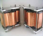
I am prototyping a pair of amorphous C core transformers (waiting on them, probably a few more weeks till they arrive), which will be interesting comparison to the M6 EI laminations. When I get them and have runs some tests I will post up the results.
Hi Stee,
Yes, putting an output transformer in there would give the whole PP output stage a nice solid reference point, then one can cut back on the negative feedback.
Have long intended to try out something like that, but not found the time yet.
Meanwhile I am putting together a new pair of monoblocks which will use the C core OP transformers, but with internal power supplies. The PSU transformers which I already have are also C core type, a bargain e*ay purchase. I have come to the conclusion that toroids for mains power are best avoided as they pass too wide a bandwith of noise and (here in London) we have very poor symmetry mains line power with appreciable DC offset which makes them hum.
Best wishes,
Susan.
Thanks for the post.
I have a NOS in sealed original boxes pair of UTC LS-667 output transformers which should be ideal for these amps. I originally bought them to use in my pair of monoblocks, but finances require the sale.... $250 + shipping...
Regret that for the UK the shipping costs would be very high.
Hope you can find someone who would like to use them.
I am prototyping a pair of amorphous C core transformers (waiting on them, probably a few more weeks till they arrive), which will be interesting comparison to the M6 EI laminations. When I get them and have runs some tests I will post up the results.
Hi Stee,
Yes, putting an output transformer in there would give the whole PP output stage a nice solid reference point, then one can cut back on the negative feedback.
Have long intended to try out something like that, but not found the time yet.
Meanwhile I am putting together a new pair of monoblocks which will use the C core OP transformers, but with internal power supplies. The PSU transformers which I already have are also C core type, a bargain e*ay purchase. I have come to the conclusion that toroids for mains power are best avoided as they pass too wide a bandwith of noise and (here in London) we have very poor symmetry mains line power with appreciable DC offset which makes them hum.
Best wishes,
Susan.
Hi Susan,
congratulations on your work. The output transformer is a crucial part (a bottleneck).
congratulations on your work. The output transformer is a crucial part (a bottleneck).
Something like this?I am prototyping a pair of amorphous C core transformers
Attachments
Sold.
I have a NOS in sealed original boxes pair of UTC LS-667 output transformers which should be ideal for these amps. I originally bought them to use in my pair of monoblocks, but finances require the sale. These are big, heavy transformers at 15lbs each, complete specs here: http://www.bunkerofdoom.com/xfm/UTC_1960_WEB/034.jpg
Pictrure here: http://www.aiko.com/images/ebay/LS-667s.jpg
$250 + shipping...
This design is almost exactly the circuit with germanium transistors that I have in my almost 40 year old Telefunken Bajazzo portable radio. Just used it today. Sounds great! PS Dick Sequerra (hi end guru) was a consultant on that project. This portable radio runs rings around ANY portable component that I have ever heard, including Class D portable circuits.
Hallo John, do you know the model number of the mentioned Telefunken Bajazzo portable radio?
by the way... the weblink of Dick Sequerra is very interesting
http://www.sequerra.com/
Hallo Susan, do you know about commercial amplifier models, what use basicly the topology of the schematic about post #1?
Perhaps the Paravicini-M100A about
Paravicini M100A Twin Tower2 and
M100A
http://www.envogue-24.de/Bilder/ear/100A Wattmeter400.jpg
http://www.envogue-24.de/Bilder/ear/100A Oben400.jpg
Here my overview of all amplifier topologies with only one kind of power devices in the output stage (yours see about number 3) :
http://www.diyaudio.com/forums/soli...better-audio-non-complements-audio-power.html
perhaps of interest
Last edited:
- Home
- Amplifiers
- Solid State
- Zero Feedback Impedance Amplifiers