apelizzo said:Hi Susan,
I put together Zeus on my bench last Saturday and on Sunday I spent all afternoon listening music. I could not leave my room. It's FANTASTIC!!!
I first start experimenting with unmatched pair of IRF540 with a 12V 2A battery as power source. Adjusting quiescent current slowly up to 50mA after that my meter showed ~2000mA. I found out that they were very unmatched 🙂
The problem went away after I got a matched pair of IRF540.
Then I start beeing more confident about switching to higher DC and I installed a pair of IXFH58N20. WOW!!
I would like to post some pictures and spectrum shots.
I'm impressed how the 100V 100W PA output toroidal transformer works for the entire spectrum as the EI is not ready yet.
Input transformer:Claritronic toroidal 30VA 2x115-0, 2x12-0
Output Transformer😛owertran (Altronics) toroidal 2x50-0, 2x24.5-0 8Ohm
Mosfet: 2 x IXFH58N20
Bias: 7805
Power supply: 25VAC 80VA toroidal, bridge, Aerovox 10.000uF 100V
Best regards,
Alfonso
Some measurements would be interesting, especially with the all toroid implementation. The IXF devices have more input capacitance (Crss) than the STW devices. From your description of the sound, that doesn't seem to be an issue. Good on ya, for the build.
Sheldon
Susan,
Pictures about my first approach to Zeus are now available.
There are two screen shots of a first set of tests. I admit this is the first time I test an amplifier so please understand... I'll try to do it right.
I built this amplifier because I was looking for the "Wire with gain" and I found it with very little can go wrong. The loudspeakers are also protected. By itself it waits to be driven in total silence just as a wire. Thanks Susan.
Test connections:
EDIROL USB Audio Line OUT -> Input Transformer -> Output Transformer -> 8Ohm speaker -> Edirol Line In
Quiescent current 100mA
I would appreciate any comment and advise.
Best Regards,
Alfonso
An externally hosted image should be here but it was not working when we last tested it.
An externally hosted image should be here but it was not working when we last tested it.
An externally hosted image should be here but it was not working when we last tested it.
An externally hosted image should be here but it was not working when we last tested it.
An externally hosted image should be here but it was not working when we last tested it.
An externally hosted image should be here but it was not working when we last tested it.
Nice use of connectors for the test jig. Your workbench is much neater than mine too. Looks like it measures well.
Sheldon
Sheldon
Hi Sheldon,
I want to thank you for all your replies and considerations.
Glad to hear that I've been useful at least for the use of connectors. Yes I could use them to match mosfets (TO220 or TO247) using the same circuit. I also use them for the multiturn trims.
Can you tell me also a little more about the measuring test I've done so far?
Also I had an idea:
If the two mosfets are not perfectly matched I suppose one will conduct more than the other and have different temperature.
I was thinking to install them on two separate identical heatsinks.
As the temperature rises would the differential constant in temperature self balance the circuit?
Best regards,
Alfonso
I'm by no means close to being expert on the measurement side. Susan has much more experience in that area. My response was "at a glance", at nothing seems untoward. It's hard to say too much without knowing some more about your test conditions. The response curve looks flat out to 20kHz, and I guess that's the limit of your equipment (computer sound card?). You don't give any power conditions, so it's hard to know much about bass response.
Again power levels for the test would be helpful but it looks like your harmonics decrease with order and beyond the 5th are better than 95dB down. Some side band noise there, but still below 90dB. The power supply is very basic, and if you wanted to reduce this some, a littler filtering would probably do so. Maybe one additional RC section with a low value resistor and a decent sized cap (play in PSUD and see what you can do with the PS ripple) Anyway, for a first bench test with and off the shelf toroids, quite good.
But hey, if it sounds good, it is.
As far as separating the transistors, hmm, probably not. You want them to track with your bias source. At least your present imbalance, to the extent it exists, will be stable. Might not be the case if you separate. Susan will chime in if I'm off base here. If you are going to wind an E-core OPT, you can make it wih a small gap. That way, a small imbalance will not cause saturation problems. I actually have a tube PP amp that is biased with an imbalance. Turns out to have the lowest distortion that way. Don't know how this circuit would work with a separate bias on each device. Maybe Susan has some thoughts here.
Sheldon
Hi Alfonso,
Thank you for sharing your pictures and graphs.
Sheldon is correct (thanks Sheldon).
Both mosfets (plus the thermal tracking one) should be on the same heatsink othersise they are likely to imballance.
Remember that as followers the tempco works against rather than for one and as they get hotter they turn on harder.
The tracking bias mosfet counters this by reducing the bias level (slightly) thus keeping things evened out (and which is why I use the same part for both the transformer driving and the bias tracking so the temcos will be the same.
Hope this helps.
Best wishes,
Susan.
Thank you for sharing your pictures and graphs.
apelizzo said:...
Also I had an idea:
If the two mosfets are not perfectly matched I suppose one will conduct more than the other and have different temperature.
I was thinking to install them on two separate identical heatsinks.
As the temperature rises would the differential constant in temperature self balance the circuit?
Sheldon is correct (thanks Sheldon).
Both mosfets (plus the thermal tracking one) should be on the same heatsink othersise they are likely to imballance.
Remember that as followers the tempco works against rather than for one and as they get hotter they turn on harder.
The tracking bias mosfet counters this by reducing the bias level (slightly) thus keeping things evened out (and which is why I use the same part for both the transformer driving and the bias tracking so the temcos will be the same.
Hope this helps.
Best wishes,
Susan.
Hi Patrick,
Thanks for the info.
When I did my original testing I didn't specifically check the tempco.
This is something I will keep in mind when I retest (when I have the time I am planing to redo several of the older test series to bring everything in line with what I am doing now to make comparison between different fets and transformers easier).
Heatsink size is also something to keep in mind, and bigger is always better. Moving up from the size I have on my test rig (300x150x40mm) to the size I used on the Zeus 75 prototype (300x300x80mm) had a big effect on reducing operating temperature.
Best wishes,
Susan.
EUVL said:If you use 2SK1529 at around 1A, it actually has negative tempco.
Cheers, Patrick
Thanks for the info.
When I did my original testing I didn't specifically check the tempco.
This is something I will keep in mind when I retest (when I have the time I am planing to redo several of the older test series to bring everything in line with what I am doing now to make comparison between different fets and transformers easier).
Heatsink size is also something to keep in mind, and bigger is always better. Moving up from the size I have on my test rig (300x150x40mm) to the size I used on the Zeus 75 prototype (300x300x80mm) had a big effect on reducing operating temperature.
Best wishes,
Susan.
Question on output transformer
Hi Susan,
I'd just like to check the connections for the Sowter 9840 output transformer I'm using. I've redrawn the info supplied by Sowter with the units and an extract from your Zeus75 .pdf
I've marked up the pdf extract with what I think are the correct connections. Could you please check and confirm? Thanks in advance.
Could you also comment on the "Provisional wire colours" diagram you have here:
http://www.susan-parker.co.uk/zeus-out-tx-75w.htm#ei150lamination
Is this supposed to tally with the colour code of the supplied transformers or have I completely misread these three diagrams?
Thanks,
James
Attachments
James;
the transformer is so squeezed between couple of source followers so you may use one from a children toy, it will scream loudly but work anyway. 😉
the transformer is so squeezed between couple of source followers so you may use one from a children toy, it will scream loudly but work anyway. 😉
Wavebourn said:James;
the transformer is so squeezed between couple of source followers so you may use one from a children toy, it will scream loudly but work anyway. 😉
Well now James, what more could you need to know about correct transformer configuration for the Zeus?
We don't need designers to create new designs, test them extensively, modify and improve them, provide detailed instructions on how to construct them, make available some key parts, and patiently answer our questions. Looks like we've been going down the wrong track all along here.
Just gut a few toys and you're done.
Sheldon
BTW: There is a nice function for members of DIY. At the bottom of each member's profile is an ignore option.
Re: Question on output transformer
Hi James,
Each of the two primary windings should have one half in each section of the bobbin, with the secondaries either as the primaries but in parallel (rather than center grounded series), or all in parallel.
I am not quite sure as to the info Sowter are supplying as I only had a preliminary test core from them some time ago (nearly 2 years!).
Can you confirm the colours of each of the two groups of windings i.e. which colours come from each of the two bobbin sections.
I do realize that the sectioned bobbin does make the wiring a bit more complex, but it does allow for the 4:1 option as well as other configuration possibilities.
Now that I have more time I will see what I can do to expand on this information on my web pages.
Many thanks.
Best wishes,
Susan.
Hi James,
nemestra said:Hi Susan,
I'd just like to check the connections for the Sowter 9840 output transformer I'm using. I've redrawn the info supplied by Sowter with the units and an extract from your Zeus75 .pdf
I've marked up the pdf extract with what I think are the correct connections. Could you please check and confirm? Thanks in advance.
Could you also comment on the "Provisional wire colours" diagram you have here:
....
Is this supposed to tally with the colour code of the supplied transformers or have I completely misread these three diagrams?
Thanks,
James
Each of the two primary windings should have one half in each section of the bobbin, with the secondaries either as the primaries but in parallel (rather than center grounded series), or all in parallel.
I am not quite sure as to the info Sowter are supplying as I only had a preliminary test core from them some time ago (nearly 2 years!).
Can you confirm the colours of each of the two groups of windings i.e. which colours come from each of the two bobbin sections.
I do realize that the sectioned bobbin does make the wiring a bit more complex, but it does allow for the 4:1 option as well as other configuration possibilities.
Now that I have more time I will see what I can do to expand on this information on my web pages.
Many thanks.
Best wishes,
Susan.
Re: Re: Question on output transformer
Hi Susan,
Sowter supply the diagram I provided on the left hand side of the
page I attached. I've now opened one of the 9840s and it is connected as follows:
Bobbin one: 1 pair green, 1 pair yellow, 1 pair orange, 1 pair grey
Bobbin two: 1 pair brown, 1 pair violet, 1 pair blue, 1 pair red
Thanks,
James
Susan-Parker said:Hi James,
Each of the two primary windings should have one half in each section of the bobbin, with the secondaries either as the primaries but in parallel (rather than center grounded series), or all in parallel.
I am not quite sure as to the info Sowter are supplying as I only had a preliminary test core from them some time ago (nearly 2 years!).
Can you confirm the colours of each of the two groups of windings i.e. which colours come from each of the two bobbin sections.
I do realize that the sectioned bobbin does make the wiring a bit more complex, but it does allow for the 4:1 option as well as other configuration possibilities.
Now that I have more time I will see what I can do to expand on this information on my web pages.
Many thanks.
Best wishes,
Susan.
Hi Susan,
Sowter supply the diagram I provided on the left hand side of the
page I attached. I've now opened one of the 9840s and it is connected as follows:
Bobbin one: 1 pair green, 1 pair yellow, 1 pair orange, 1 pair grey
Bobbin two: 1 pair brown, 1 pair violet, 1 pair blue, 1 pair red
Thanks,
James
Re: Re: Re: Question on output transformer
Hi James,
Okay, I happen to have the Sowter transformer bobbin in my test rig at the moment - so some assurance it can work.
My primaries are wired:
================
MOSFET to Grey
Mauve+Yellow
Brown+Grey(1) to GND
Mauve(1)+Yellow(1)
MOSFET to Brown(1)
Secondaries:
===========
Red+Orange = +Ve Out
Blue+Green = -Ve Out
Red(1)+Orange(1) = +Ve Out
Blue(1)+Green(1) = -Ve Out
Note that I have these two pairs on separate sets of binding posts so I can easily change from 2:1 to 4:1 step down.
=======
I usually put a low level sinewave source on one winding and check the others for phase on my scope as I "build" the configuration up with terminal blocks.
Hope this helps?
Best wishes,
Susan.
Hi James,
nemestra said:Hi Susan,
Sowter supply the diagram I provided on the left hand side of the
page I attached. I've now opened one of the 9840s and it is connected as follows:
Bobbin one: 1 pair green, 1 pair yellow, 1 pair orange, 1 pair grey
Bobbin two: 1 pair brown, 1 pair violet, 1 pair blue, 1 pair red
Thanks,
James
Okay, I happen to have the Sowter transformer bobbin in my test rig at the moment - so some assurance it can work.
My primaries are wired:
================
MOSFET to Grey
Mauve+Yellow
Brown+Grey(1) to GND
Mauve(1)+Yellow(1)
MOSFET to Brown(1)
Secondaries:
===========
Red+Orange = +Ve Out
Blue+Green = -Ve Out
Red(1)+Orange(1) = +Ve Out
Blue(1)+Green(1) = -Ve Out
Note that I have these two pairs on separate sets of binding posts so I can easily change from 2:1 to 4:1 step down.
=======
I usually put a low level sinewave source on one winding and check the others for phase on my scope as I "build" the configuration up with terminal blocks.
Hope this helps?
Best wishes,
Susan.
Hi Susan,
yes thanks for this. I'll redraw the diagram over the next couple of days and try building up the output as you have suggested at the weekend.
Thanks,
James
yes thanks for this. I'll redraw the diagram over the next couple of days and try building up the output as you have suggested at the weekend.
Thanks,
James
Line driver
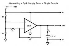
I'm experimenting with DRV134 to drive the input transformer. It requires +/- 15V though. Zeus has a single voltage supply that means I have to build a new +/15V rail using Transformer LM7815 LM7915 bla bla. Would it more convenient using LM675 as voltage splitter?
I'm experimenting with DRV134 to drive the input transformer. It requires +/- 15V though. Zeus has a single voltage supply that means I have to build a new +/15V rail using Transformer LM7815 LM7915 bla bla. Would it more convenient using LM675 as voltage splitter?
Attachments
Re: Line driver
Hi,
Could do it that way, will involve capacitive coupling but you might need to do that anyway depending on your source.
I have tried the SSM2142 which didn't do so well driving the input 1:10 step up transformer. I don't know if the DRV134 will do better although the data sheet does say "IMPROVED REPLACEMENT".
Might be best to try a bench lash up to check before making the effort to build everything nicely.
The DRV134 would be fine with a 2 stage Zeus as the input is then 1:2+2.
Please let me know how it goes.
Best wishes,
Susan.
Hi,
apelizzo said:I'm experimenting with DRV134 to drive the input transformer. It requires +/- 15V though. Zeus has a single voltage supply that means I have to build a new +/15V rail using Transformer LM7815 LM7915 bla bla. Would it more convenient using LM675 as voltage splitter?
Could do it that way, will involve capacitive coupling but you might need to do that anyway depending on your source.
I have tried the SSM2142 which didn't do so well driving the input 1:10 step up transformer. I don't know if the DRV134 will do better although the data sheet does say "IMPROVED REPLACEMENT".
Might be best to try a bench lash up to check before making the effort to build everything nicely.
The DRV134 would be fine with a 2 stage Zeus as the input is then 1:2+2.
Please let me know how it goes.
Best wishes,
Susan.
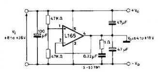
Sorry if I didn't exlain well the idea.
The intention of using of the LM675 or L165 was just to avoid building another power supply just for the driver stage and not for driving the input transofmer with capacity coupling. I tried driving the input transformer with single amplifier with capacity coupling with disappointing results.
So the LM675 would provide a new +15/-15 volts rail from Zeus main single voltage power supply. The +15/-15 could be suitable for any driving device, AD815, DRV134 etc.
Attachments
Hi,
No appolagies necessary. It is I who didn't write clearly.
Yes, splitting the power as you sugest is fine, and of course the transformer primary can sit happily at the c. 15 volts mid level.
You might want to pre-regulate the +volts from the power stage supply to get rid of the main ripple component and also ensure that the supply volts doesn't go over the opamps +- Vmax. Mosfet follower with a zener and pullup should be enough.
Also can use this pre-reg supply for the bias generator. Then you arn't limited to 40 volts max.
The input to the line driver (AD815, DRV134...) would be cap coupled, but we often have to make that compromise to get rid of DC ofset anyway.
Best wishes,
Susan.
apelizzo said:Sorry if I didn't exlain well the idea.
The intention of using of the LM675 or L165 was just to avoid building another power supply just for the driver stage and not for driving the input transofmer with capacity coupling. I tried driving the input transformer with single amplifier with capacity coupling with disappointing results.
So the LM675 would provide a new +15/-15 volts rail from Zeus main single voltage power supply. The +15/-15 could be suitable for any driving device, AD815, DRV134 etc.
No appolagies necessary. It is I who didn't write clearly.
Yes, splitting the power as you sugest is fine, and of course the transformer primary can sit happily at the c. 15 volts mid level.
You might want to pre-regulate the +volts from the power stage supply to get rid of the main ripple component and also ensure that the supply volts doesn't go over the opamps +- Vmax. Mosfet follower with a zener and pullup should be enough.
Also can use this pre-reg supply for the bias generator. Then you arn't limited to 40 volts max.
The input to the line driver (AD815, DRV134...) would be cap coupled, but we often have to make that compromise to get rid of DC ofset anyway.
Best wishes,
Susan.
- Home
- Amplifiers
- Solid State
- Zero Feedback Impedance Amplifiers