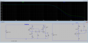
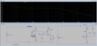
I am unsure if this is possible with real components. But appreciate if someone look at it and comment. PSRR is very high. And noise acceptable.
Attachments
Last edited:
I'm hope that you are not refering to TL431 @ 1mA bias with 5V supply? Due to divider, the TL are internally disabled without any gain, and probably will show 2V (1mA times 2000R) between cathode/anode (a little less than that due to internal biasings). So the 3µ3V is residual from the biasings and thermal noise etc.6.8V zener at low bias vs. TL431 at low bias, I meant.
The 20µV @ 2V5 relays accordingly when the device are operational at 5V (5mA up; 40µV noise).
Versus the 6V8 specimen, the TL will have probably 55µV of noise at 6V8 and the zener 21µV, then.
I believe that you know that but costs nothing to mention this in case another fellow like me are reading all these pages (sometimes I read entire topic when is not soo long).
Most zeners are variable in this regards, and some brands have LESS noise at gray "avalanche-zener" zone (5V6-6V8). The TL at least have the 20µV/2V5 more consistently from maker to maker or batch to batch, although for me is more fun to play with discrete components (fun for others, nightmare for some)...
PS.:
Old thread, but with good information like these measurements from another pages. I arrived here first.
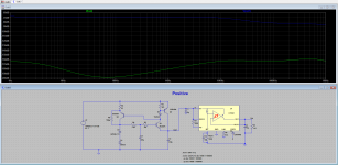
BTW about the topic. Remember that open loop series regulator will show output impedance that varies with load, being higher for low currents. Theorically 1/gm of the device at operating current. For constant or low varying current loads like most preamps, no big deal.
So when one asks me "about this O/L series reg out Z" I say, "at what load current"?
So when one asks me "about this O/L series reg out Z" I say, "at what load current"?
- Status
- Not open for further replies.