Hello all,
in the original zen amp, p1 and r8 (take a look at the picture) form the feedback loop.
what would happen if i take them out. could i damage my speakers?
i suppose that the amp will have less power (how much?, one or two watt?), much more distortion and probably no damping factor anymore. what else can i expect?
after all, it's not much work to take out both parts, so if i can't damage my speakers, i think i will give it a try. i use the amp for my jbl 2446 horn drivers, so power is not a problem.
have a nice day
lilmik
Attachments
The 2 parts you want to remove also set the bias for the FET.
How will you bias the FET to set the idle current?
You could move the top of r8 up to the + power rail and increase it's value. The problem is that now the bias will drift with temp. Not only is the feed back for the signal but the bias as well.
BZ
How will you bias the FET to set the idle current?
You could move the top of r8 up to the + power rail and increase it's value. The problem is that now the bias will drift with temp. Not only is the feed back for the signal but the bias as well.
BZ
It works fine, if you want a current source.
The way to go on this is to make P1 and P8 very high values,
greater than 200 Kohm or so, and use a smaller (film) input
capacitor. This will allow some feedback for DC biasing, but
will not allow significant feedback for AC purposes, as the
impedance of the signal source will be very small compared to
those values. You now have a high gain current source. To
lower the gain into, say 8 ohms, I suggest a resistance value
on the Source of Q1 about .5 to 1 ohms (power resistor) which
will lower the gain to a more suitable number.
Connect the R-8 to the supplyline (+) and add a 0,47 to 1 ohm power resistor between FET-source and ground. That way you will have resonable gain and lower distortion and very high output impedance. I have treid this and it sounded very nice. The dampingfactor of the amp was very low.
Circlomanen said:Mr Pass, you posted while I typed!
Im to slow!!
Ya, same here as I added to my post.
BZ
hello,
thanks everyone for your quick reply.
so:
1) deacreasing the input cap,
2) increasing p1 and r8 and
3) adding a source-resistor.
if i do this, the new schematic looks like figure 1 in the picture below.
i am note sure about "moving the top of r8 up to the + power rail".
if i do the things above and 'move r8 to the + power rail', the new schematic looks like figure 2 in the picture below.
what's correct?
have a nice day
lilmik
Attachments
Hmm..I'd also be interested to know which one works better.
Fortunately, there are not many permutations🙂
If you try both, let us know which one you chose.
Unless the Master uncovers the truth...😀
Fortunately, there are not many permutations🙂
If you try both, let us know which one you chose.
Unless the Master uncovers the truth...😀
Vix said:
If you try both, let us know which one you chose.
I tried both , I chose R8 attacched to the current source . fig 1
stefanobilliani said:I tried both , I chose R8 attacched to the current source . fig 1
Referencing figure 1, I recommend reducing R5 to as low as
221 ohms. Also, I would place 221 ohms in series with the
Zener diode to help avoid parasitic effects.
Hi!
I asked couple of months ago the same about no feedback, for the Zen Lite, but the answers was not too much....
Now I am very happy that I can see here something practical suggestions!
So, I would like to ask here: the suggestions of Mr. Pass and Circlomanen are also true for the ZenLite???
I built the ZenLite already, and it is my favorite! but/and I would like to try anyway without feedback, to compare the 2 different variations and to find out which design methode I like more.
Until now I find out (for myself) I like: Class A more then Class AB, SE more than PP, Fet more then Bipolar, etc.... and Pass amps more than ANYTHING 🙂
Now I need to know only one more thing: Feedback or not to Feedback? This is the question... 🙂) Which I like more?
Thanks!
Greets:
Tyimo
P.S.: Mr Pass! When will come out your new ZenLite variation about you wrote some month ago?
Tyimo said:So, I would like to ask here: the suggestions of Mr. Pass and Circlomanen are also true for the ZenLite???
The approach I mentioned applies to all the Zens so far. Just
remember that they become current sources when you take out
the feedback. You can give them a finite output impedance by
loading them with resistance to ground at the output.
😎
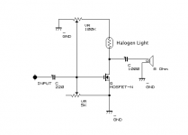
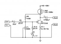
Here's a little variation on the Zen Lite that I throw together on a bread board when i want some music and no working amplifier is close. I have a 300W halogen bulb (used in utility lights) that has two wires soldered onto the ends of the tubular bulb. I just keep it in my parts boxs. Was a bear to solder the wires in place due to the ceramic ends of the bulbs being like little heat sinks🙄
Might be a little unorthodox, but I've always liked this little amp. Usually powered from +20V:
Might be a little unorthodox, but I've always liked this little amp. Usually powered from +20V:
Attachments

Hi,
Referencing to LilMik's fig.1 ...I was wondering...What would be the input impedance of that circuit? (assuming only 220 Ohm at the Gate)
I have tried something similar, and noticed that the gain was too high (with 1 ohm 5w source resistor) to be used with Bride of Zen. In fact , I could use feed the amp directly from the source (CD player), only with the pot at the input (50k). But I had trouble setting the bias, now I see that I should have increased bias resistors....
However, I am thinking about adding a buffer at the input (like on ZEN V4). What do you think, will it improve the performance here?
And....I see that in that case the Bride of Zen becomes needless...(or maybe it can be converted to a follower)...
Best regards,
Vix
Vix said:Hi,
I have tried something similar, and noticed that the gain was too high (with 1 ohm 5w source resistor) to be used with Bride of Zen. In fact , I could use feed the amp directly from the source (CD player), only with the pot at the input (50k).
I do not use pramp either . But I do use the eq network at the output .
Vix said:
However, I am thinking about adding a buffer at the input (like on ZEN V4). What do you think, will it improve the performance here?
No , in my experiments I find that adding the buffer increases the gain to very high levels , for sure it will comes down to use some feedback controlling it ...
By the way I have a very nice CS with Aleph CS , very low power ,
very low voltage supply . It is giving me more and more than I actually expect being
very small class A amp .
I am using it with the Fostex 206 , and Grado headphones .
I builded it in a metal enclosure that , for the size , has the resemblance of a shoes box.
Go figure
😎
Attachments
HI Stefano! Looks very nice!
BTW, once I have built a small amp in the NIVEA creme tin. It was a chipamp, nothing special. It was working for some time in my office. Most people who saw it found it very interesting. I was a bit disapointed. If I had brought a ZEN, which is uglier, but sounds much better, it would't be so appreciated
Lesson: Appearance matters!!!
Back to the topic, the reason I am so curios about current ZEN is that i have FOSTEX 206E speakes in the ML TL enclosure. I have built them together with a friend of mine. Can be seen here:
http://www.quarter-wave.com/Gallery/Gallery.html
(it is the seventh from the top -"Built by Viktor Halili and Artan Ymeri")
So they are a perfect candidate for this amp. At the moment they are working with ZEn v3, which is waiting for Nelson's article on trasconductance ZEN, and will be converted. Or, if i get enough tips from this thread, I may do this even earlier.
It seems like Nelson is too busy, or I am being too impatient. Or both...
Best regards
Viktor
The FE206E is an excellent candidate for this sort of thing -
check out the commentary on loading the amp in the article
on www.firstwatt.com as you will probably find that you want
to put some resistance and perhaps an RC network across the
speaker to tailor the response. Driven by a pure current source
you will probably find it boomy. Also it is helpful to experiment
with the stuffing.
😎
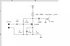
Going out to my work bench I found some Mosfets that I thought were blown. I tested them with a DMM and they apeared to be Okay. Well, I figured I better test them a little better so why not with a variation of the circuit being described here. So, I loaded up the bread board and began tinkering... BTW all the mosfets that showed to be alright with the DMM in fact worked. I had 3 2sj352s and one 2sk1529. I started with the 2sk1529 and wasn't all that thrilled with the sound so I switched to the 2sj352s. These sounded much better with this type of circuit. The finalized Schematic is attached. Note that these are P types, so it is a negative supply of about -24V and the polarity of the capacitors is reversed. I also added a source bypass capacitor which increased the gain ever so slightly (much like it does with a tube). I like the sound of this little amp and may actually build up a real one.
Attachments
- Status
- Not open for further replies.
- Home
- Amplifiers
- Pass Labs
- zen without feedback